NASA Noise Prediction Tool Supports Users in Air Taxi Industry

NASA Noise Prediction Tool Supports Users in Air Taxi Industry

1 min read

Preparations for Next Moonwalk Simulations Underway (and Underwater)

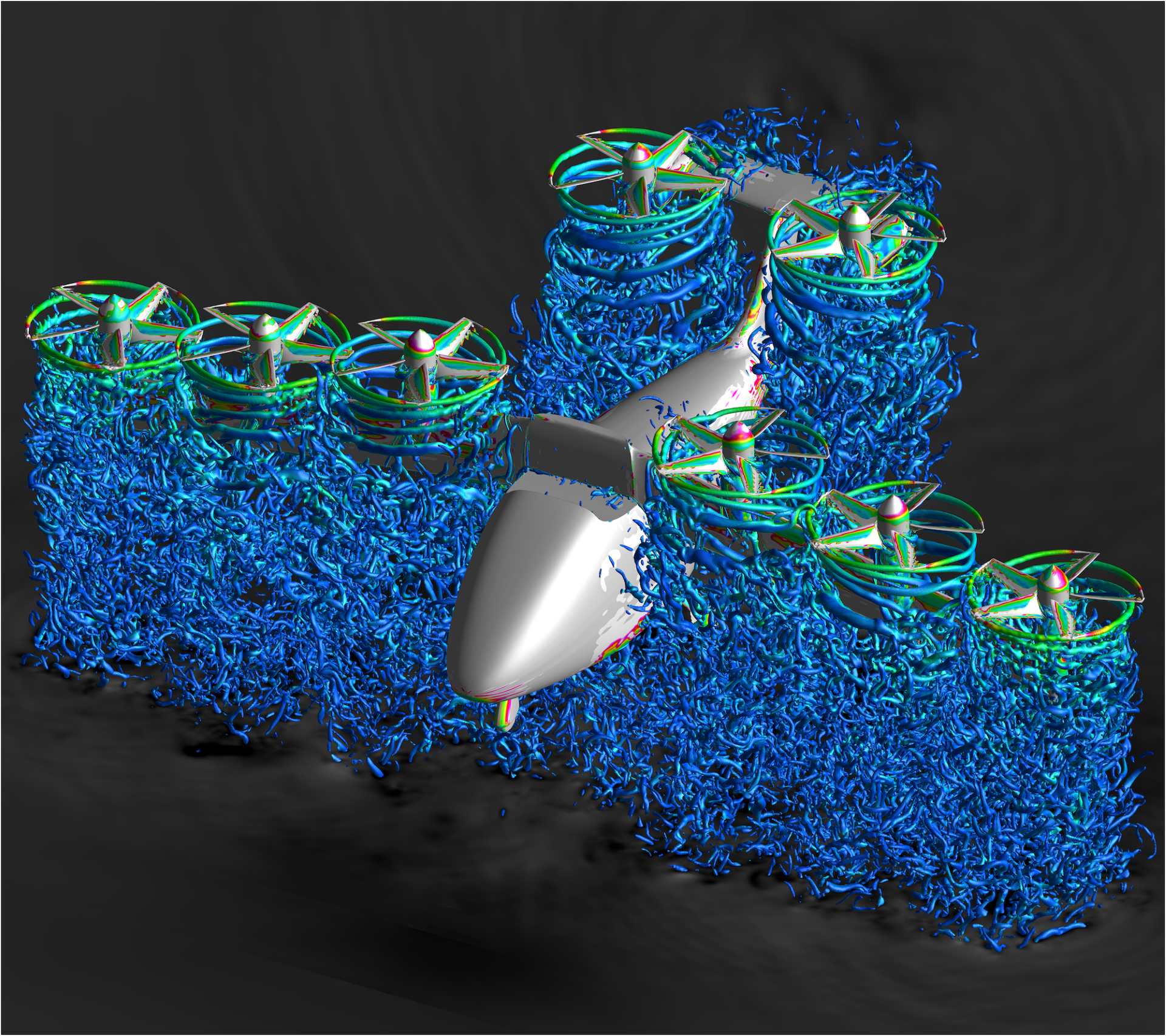
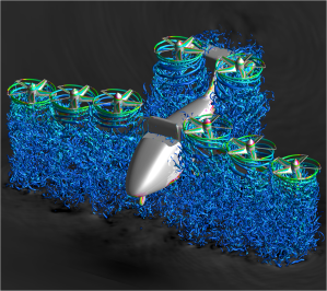
A silver aircraft model with eight propellors hovers in this image with green circles showing the motion of air moving around the propellor and blue waves flowing below showing the motion of air coming from the propellors down to the ground.
The results from a NASA software tool called OVERFLOW, used to model the flow of air around aircraft, are shown in this image.
NASA

Several air taxi companies are using a NASA-developed computer software tool to predict aircraft noise and aerodynamic performance. This tool allows manufacturers working in fields related to NASA’s Advanced Air Mobility mission to see early in the aircraft development process how design elements like propellors or wings would perform. This saves the industry time and money when making potential design modifications.

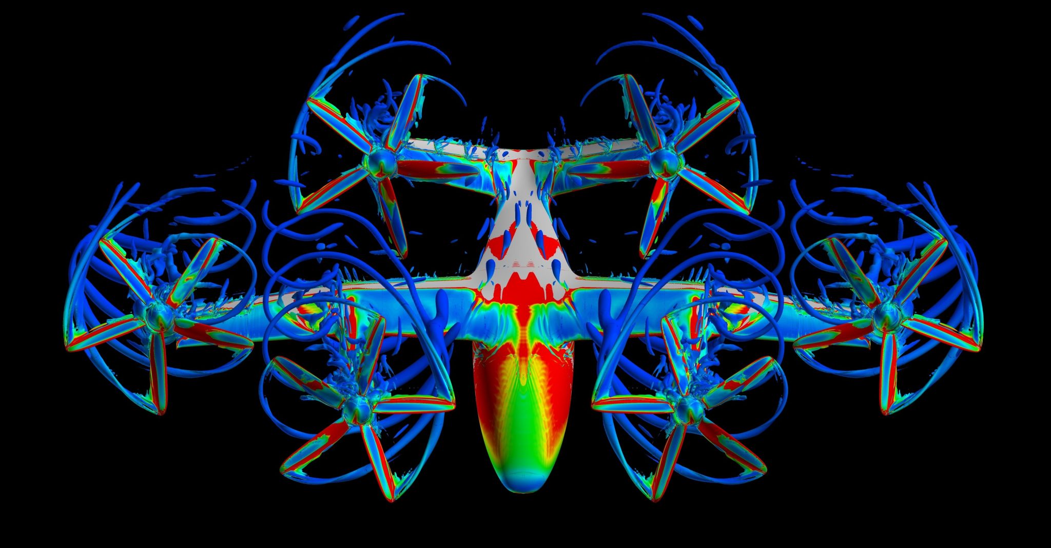
This NASA computer code, called “OVERFLOW,” performs calculations to predict fluid flows such as air, and the pressures, forces, moments, and power requirements that come from the aircraft. Since these fluid flows contribute to aircraft noise, improved predictions can help engineers design quieter models. Manufacturers can integrate the code with their own aircraft modeling programs to run different scenarios, quantifying performance and efficiency, and visually interpreting how the airflow behaves on and around the vehicle. These interpretations can come forward in a variety of colors representing these behaviors.

This computer program is available to industry for U.S. release via the software.nasa.gov website.

A silver aircraft model with six propellors hovers in this image and is covered in red, green, yellow, and blue colors showing the motion of air moving around the aircraft. The blue propellors show the blades are in motion.
An OVERFLOW modeling image from the manufacturer Joby Aviation.
Joby Aviation
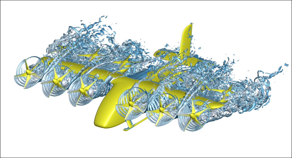
A yellow aircraft model with six propellors is shown in motion in this image as it hovers. Silver waves come off of the aircraft propellors to show it in motion.
An OVERFLOW modeling image from the manufacturer Wisk.
Wisk
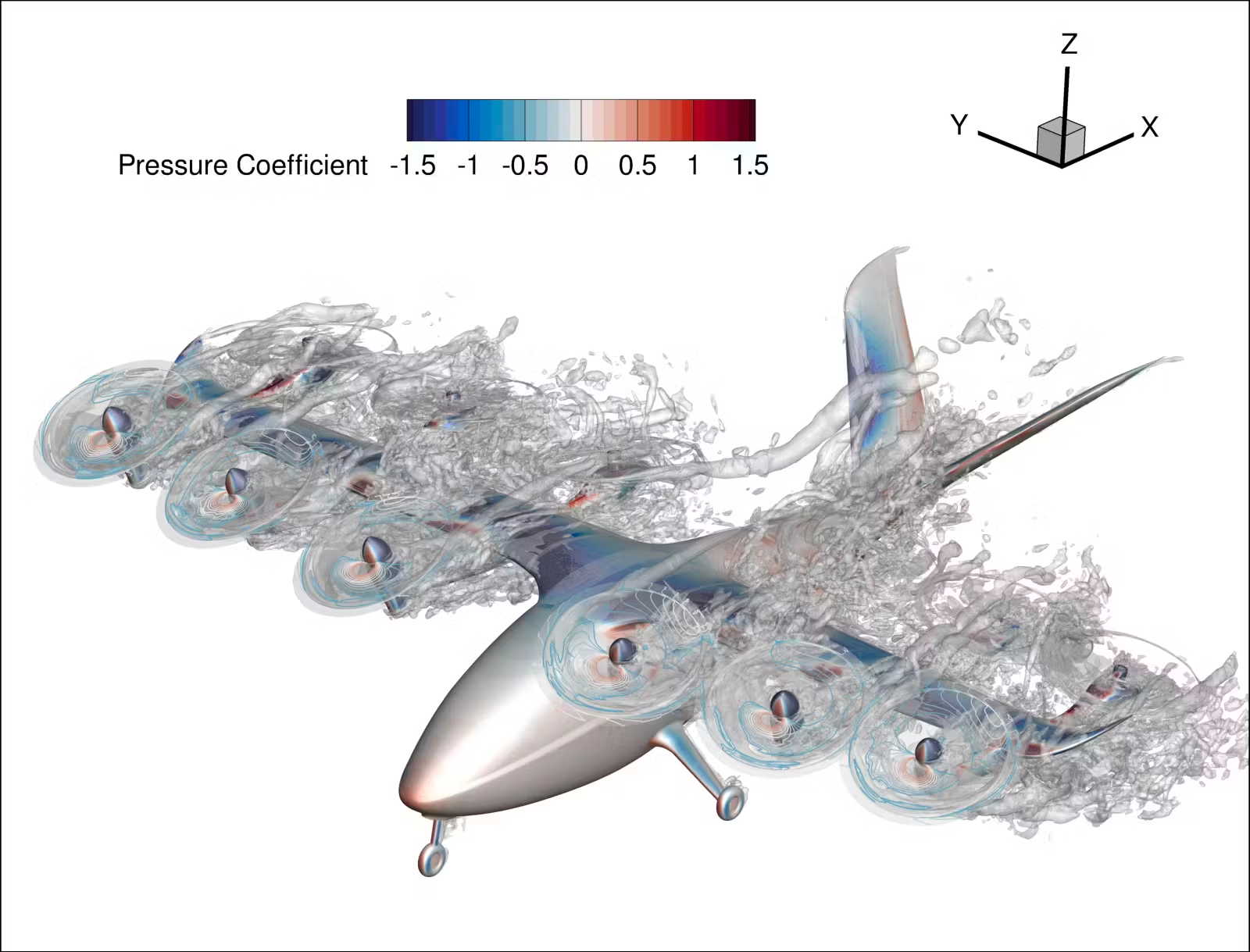
A silver aircraft model with six propellors hovers in this image with blue and red streaks as well as silver are moving off of the aircraft showing the propellors in motion as air is flown off of the aircraft propellors.
An OVERFLOW modeling image from the manufacturer Archer Aviation.
Archer Aviation

Powered by WPeMatico

Get The Details…
Dede Dinius

Save-The-Date: DoD-NASA Lidar Technical Interchange Meeting (TIM)

Save-The-Date: DoD-NASA Lidar Technical Interchange Meeting (TIM)

2 min read

Preparations for Next Moonwalk Simulations Underway (and Underwater)

Details

DoD-NASA Lidar TIM

August 13-15, 2024

MIT Lincoln Laboratory in Arlington, VA (Crystal City)
241 18th St S, Arlington, VA 22202

MIT Lincoln Laboratory is hosting a TIM between NASA and DoD to facilitate the sharing of lidar knowledge between these institutions and identify potential areas of collaboration that maximally utilizes the strengths from each organization. This TIM will provide an opportunity to discuss common issues and challenges and possible solutions.

Objectives

This TIM will include up to CUI-level presentations and discussions from leaders in lidar technology development and application.

  1. Share DoD & NASA capabilities in lidar systems, technologies, processing and exploitation/analysis with DoD community & NASA centers, including JPL and NASA headquarters.
  2. Identify NASA and DoD mission and sensor needs that could leverage existing lidar investments to satisfy requirements.
  3. Connect NASA and DoD lidar practitioners, experts and end-user communities and
  4. Roadmap at least two potential applications for collaborative opportunity. Briefings will only include up to CUI level, and representatives from the NASA Centers, JPL, and various DoD organizations (FFRDCs, UARCs, service laboratories, and user community) will be invited to participate.  

Co-Chairs

M. Jalal Khan (MIT-LL), T.Y. Fan (MIT-LL), Jessica Gaskin (NESC), Upendra Singh (NESC), and Parminder Ghuman (GSFC)

More information

Coming soon!

Share

Details

Last Updated

Apr 04, 2024

Powered by WPeMatico

Get The Details…
Daniel Hoffpauir

Tech Today: Synthetic DNA Diagnoses COVID, Cancer

Tech Today: Synthetic DNA Diagnoses COVID, Cancer

2 min read

Preparations for Next Moonwalk Simulations Underway (and Underwater)

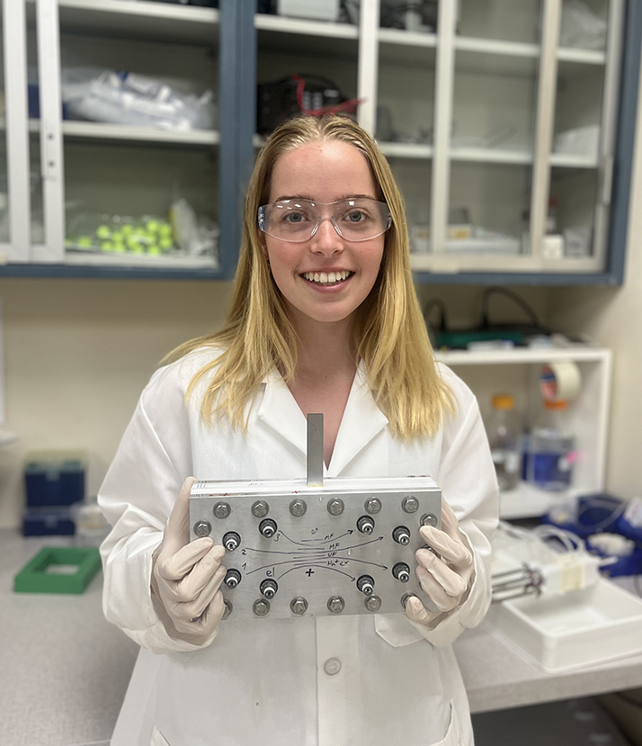
Princeton University undergraduate Kate Sheldon in a lab, holding a rectangular device in both hands
Princeton University undergraduate Kate Sheldon, doing summer work at Firebird Diagnostics, holds a prototype of the Agnostic Life Finder, or ALF, which was developed to seek life on Mars without making Earth-specific assumptions about molecular biology.
Credit: Firebird Diagnostics LLC

At first glance, the search for life beyond Earth might not seem related to human illness, but to biochemist Steven Benner, the connection is clear.

“In diagnostics for an infectious disease, you’re looking for alien life inside of a patient,” said Benner, who has spent nearly two decades conducting NASA-funded research on what alien life might look like at the molecular level.

“It’s actually a bit easier to build a diagnostics assay to detect COVID than to build an agnostic life finder to search for Martian DNA, whose structure would be unknown,” he said.

Benner is the co-founder and CEO of Firebird Diagnostics LLC, based in Alachua, Florida, which sells synthetic DNA and molecule packages to researchers, who use them to develop tools to detect and treat ailments like cancer, hepatitis, and HIV. The company also sold COVID tests during the pandemic.

Benner holds that while some of what we know about biochemistry on Earth may be universal, most is Earth-specific. He and his partners developed DNA-like molecular systems with six and eight nucleotides, or building blocks, based on research funded partly by NASA’s Astrobiology Program. These systems add to the four building blocks in Earth-based DNA an additional two or four synthetic nucleotides.

Mary Voytek, head of the Astrobiology Program at NASA Headquarters in Washington, said Benner’s work shows there are alternatives to Earth-based biological molecules, “This helps us understand what else is possible and may be found in life beyond Earth.”

Share

Details

Last Updated

Apr 04, 2024

Powered by WPeMatico

Get The Details…
Andrew Wagner

NASA Wallops to Launch Three Sounding Rockets During Solar Eclipse 

NASA Wallops to Launch Three Sounding Rockets During Solar Eclipse 

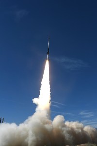
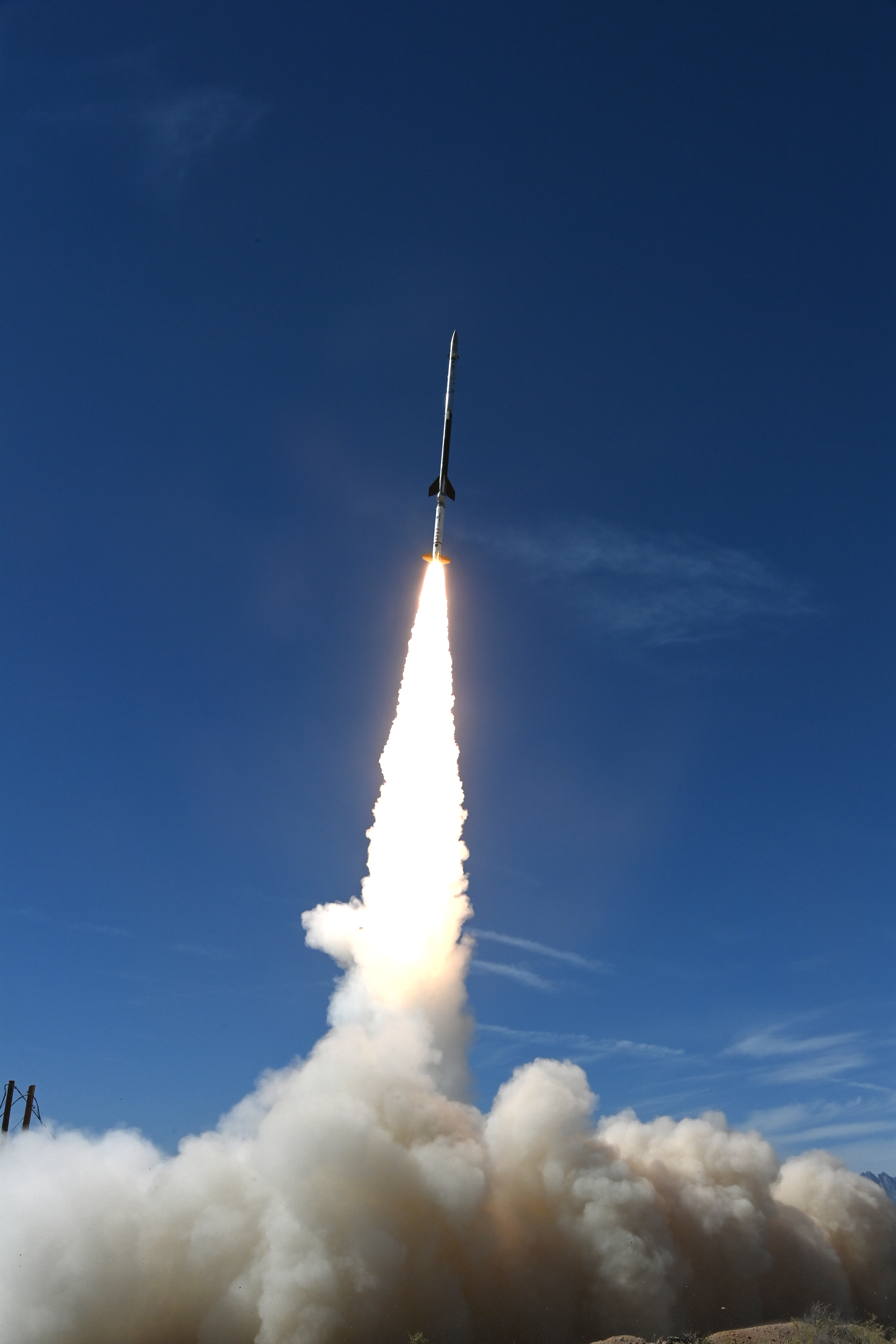
Three Black Brant IX sounding rockets for the Atmospheric Perturbations around Eclipse Path (APEP) mission are scheduled to launch from NASA’s Wallops Flight Facility launch range in Virginia. The launch window opens April 8, 2024, at 2:40 p.m. EDT.  

Launching approximately 45 minutes before, during, and after the peak local eclipse, the APEP sounding rockets will study how Earth’s upper atmosphere is affected when sunlight momentarily dims over a portion of the planet. Targeted launch times for the three rockets are 2:40 p.m., 3:20 p.m., and 4:05 p.m. but may be subject to change. 

The launches will be livestreamed on Wallops’ YouTube beginning at 2:30 p.m.  

Weather permitting, the launches may be visible in the mid-Atlantic region. Remember to always wear solar safety or “eclipse” glasses when looking at the Sun to protect your eyes. For the Wallops area, the eclipse will begin around 2:06 p.m. The Moon will block 81.4% of the Sun’s light at peak local eclipse at 3:23 p.m. and conclude at 4:34 p.m. 

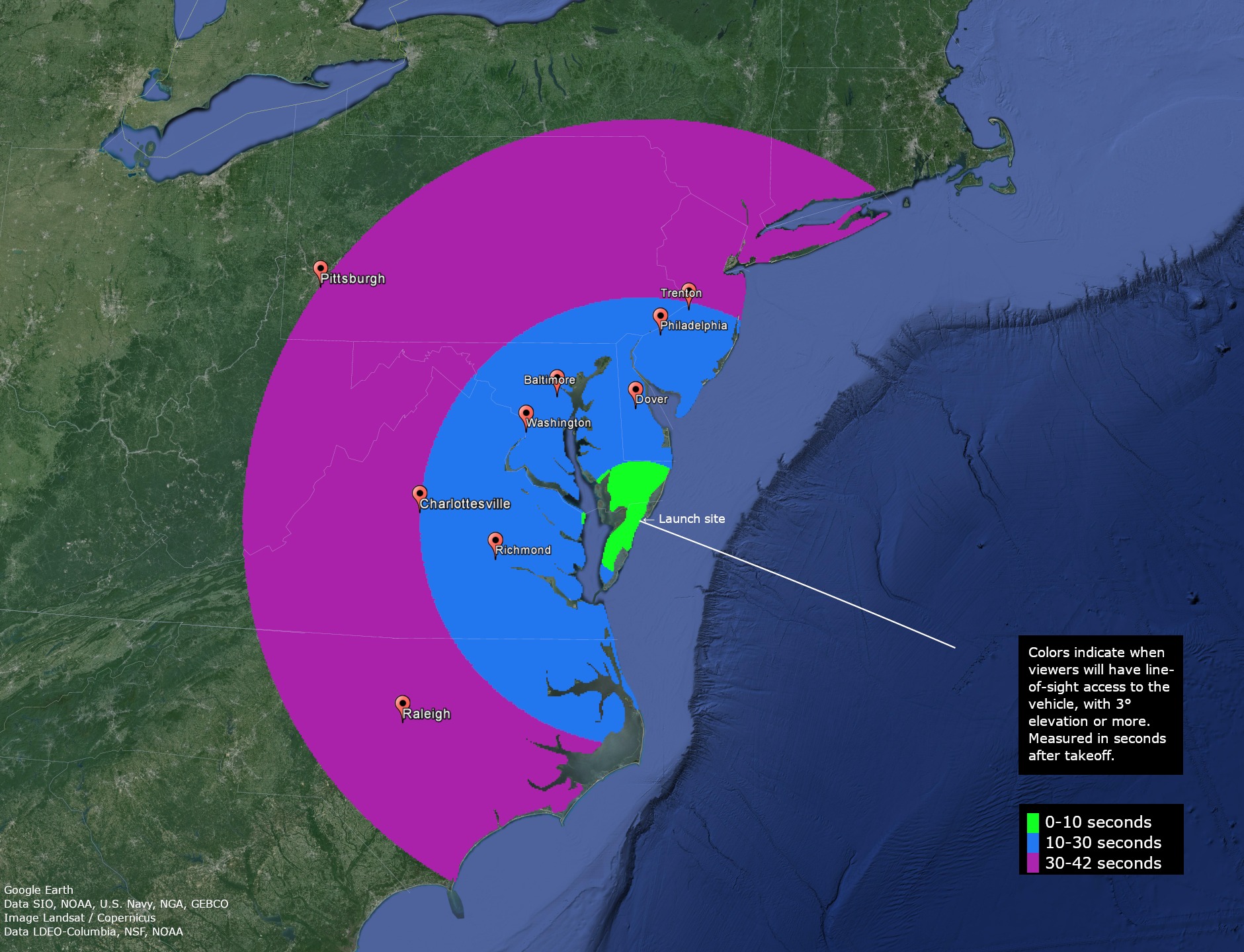
A visibility map showing the mid-Atlantic region. The map shows how many seconds after that people in the area may be able to see the Black Brant IX sounding rocket in the sky.  The land is green and the ocean is dark blue. Visibility of 30-42 seconds is represented by a bright pink semi-circile reaching up to eastern Massachusetts, through most of Pennsylvania, through eastern West Virginia, Virginia and North Carolina. Visibility area for viewers with a line-of-sight 10-30 seconds after launch is a blue semi-circle reaching from middle of New Jersey down to north North Carolina and inland to Virginia. Visibility from 0-10 seconds is indicated by a bright green semi-circle mostly covering to the edge of the southern border of Delaware and down into the Eastern Shore of Virginia. City labels starting north at Trenton, Philadelphia, Dover, Baltimore, Washington, Pittsburgh, Charlottesville, Richmond, and Raleigh. On the right is a black box with white words: "Colors indicate when viewers will have line-of-sight access to the vehicle, with 3° elevation or more. Measured in seconds after takeoff.
Launch viewing map forAtmospheric Perturbations around Eclipse Path mission are scheduled to launch from NASA’s launch range at Wallops Flight Facility in Virginia on April 8, 2024.
Credit: NASA

Members of the public are invited to the NASA Wallops Visitor Center on Monday, April 8, to view the sounding rocket launches and the partial eclipse. Gates to the visitor center will open from 1-5 p.m. and will close once parking lot capacity is reached. For those traveling to our visitor center, all vehicles MUST fit within a standard parking spot for this event; no large, oversized vehicles or buses will be allowed for entry. 

The visitor center will offer solar-related activities, have NASA sounding rocket experts onsite to answer questions, and host Globe Program expert Brian Campbell, who will be showing people how to collect data during the eclipse using the Observer app. Eclipse glasses and pinhole viewers will be available during this event while supplies last. Food trucks will be onsite serving food and drinks, including empanadas, crab cakes, hamburgers, hot dogs, barbecue, water ice, and more. 

While this combined viewing event is exciting for some, it may not be ideal for all. A designated sensory-friendly quiet area will be available at the Wallops Visitor Center for guests. This supervised quiet area will include dimmed lighting, seating, a reflection area, and touch items for guests to explore. 

Prepare for safe solar viewing during this year’s eclipse by checking out NASA’s Eclipse Safety page

Media Contact
Amy Barra 
NASA’s Wallops Flight Facility, Wallops Island, Virginia

Share

Details

Last Updated

Apr 04, 2024

Editor
Madison Olson
Contact
Location
Wallops Flight Facility

Powered by WPeMatico

Get The Details…
Madison Olson

Advances in Understanding COPV Structural Life 

Advances in Understanding COPV Structural Life 

The Structures Technical Discipline Team (TDT) was involved in numerous investigations this past year, but composites, fracture mechanics, and pressure vessels dominate the list. All three of these specialties are important to composite overwrapped pressure vessels (COPV). One of the TDT’s most important findings this year was the exposure of an inherent vulnerability that underpredicts structural life, driven by current specifications and testing standards for COPVs. This NESC work and its recommendations will significantly improve safety and mission success for all current and future COPV operations throughout the aerospace community. 

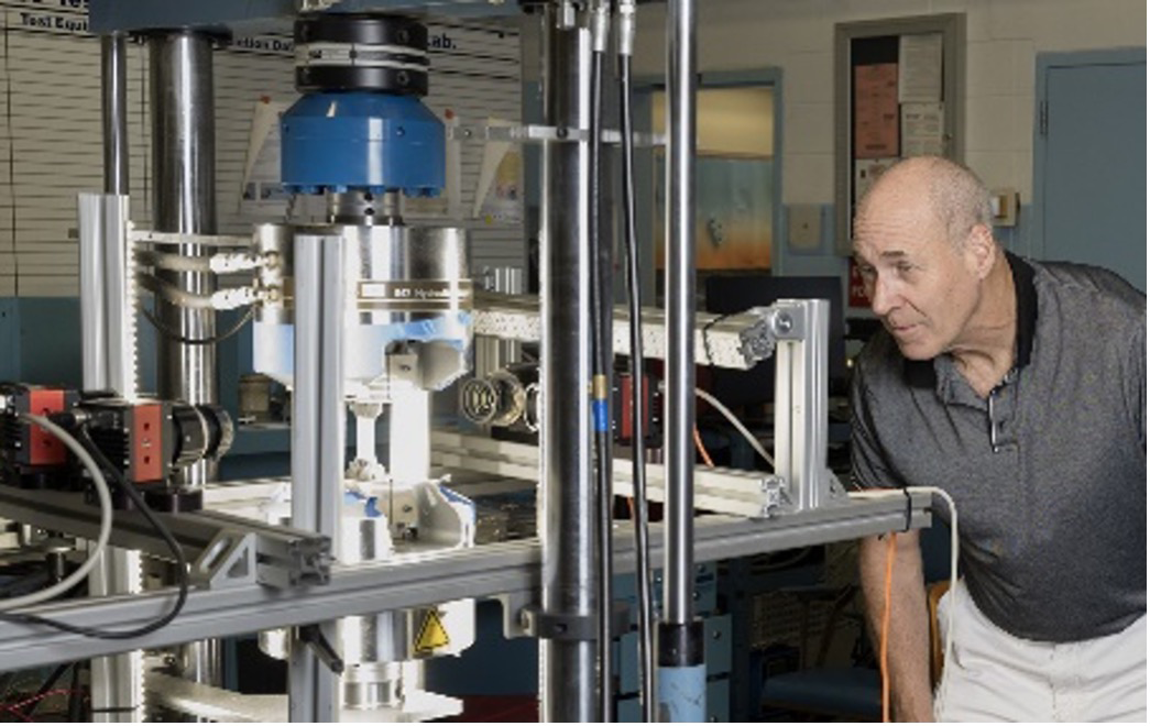
Dr. David Dawicki employs digital image correlation to evaluate strain in metallic coupons. 

Damage Tolerance Analysis Standard Can Be Unconservative for COPVs 

COPVs consist of a metallic liner that contains the fluid or gas and a composite overwrap that provides strength (Figure 1). The operational pressure cycles for a spaceflight COPV generally starts with an initial overpressure, called an autofrettage cycle, that yields the metallic liner, while the stronger composite overwrap remains elastic. Liner yielding during autofrettage results in a small amount of liner growth, resulting in liner compression when the COPV is depressurized after autofrettage. The subsequent operational cycles can be either elastic (elastically responding COPV) or elastic-plastic (plastically responding COPV).
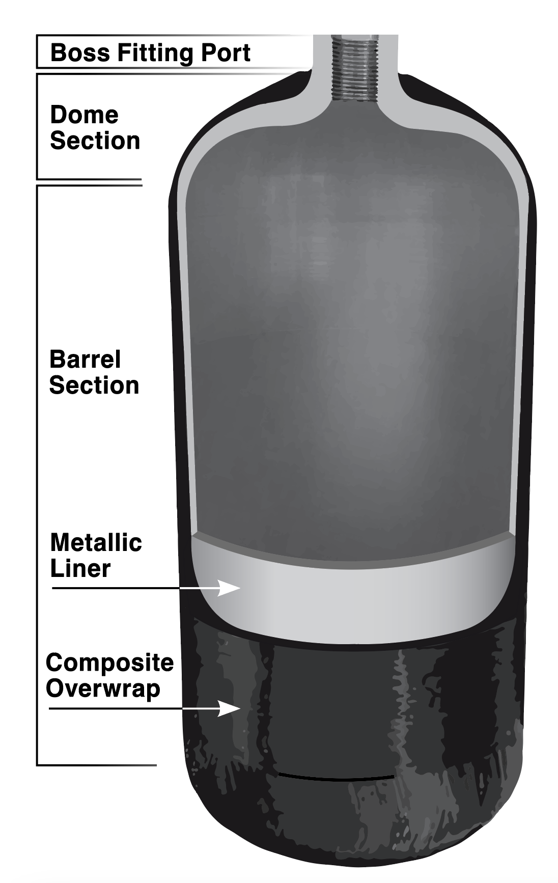
  Figure 1.Illustration of COPV major components.

The damage tolerance life evaluation of spaceflight COPVs is governed by the ANSI/AIAA-S-081B, Space Systems–Composite Overwrapped Pressure Vessels. This standard provides the baseline requirements for damage tolerance analyses (DTA) of COPVs with elastically responding liners. The standard allows the DTA to consider the influence of the elastic-plastic autofrettage cycle independently of the elastically responding cycles. The elastically responding cycles are permitted to be analyzed using linear elastic fracture mechanics (LEFM) tools like the NASGRO crack-growth analysis software. The standard states that the DTA must not consider any beneficial influences of the autofrettage cycle on the subsequent elastically responding cycles but does not consider the possibility of detrimental influences of the autofrettage cycle.  

In the study, Unconservatism of Linear-Elastic Fracture Mechanics Analysis Post Autofrettage (NASA/TM-20230013348), an NESC team conducted a combined experimental and analytical investigation into the influence of the autofrettage cycle on subsequent elastic cycles. Tests were conducted on coupons with part-through surface cracks that were subjected to cyclic loading that was representative of the operational cycles of a COPV liner. Half of the tests were conducted with the full loading history (including the autofrettage cycle) and the other half were identical except that the autofrettage cycle was omitted. Cracks in the tests with the autofrettage cycle grew faster than cracks in the identical tests that excluded the autofrettage cycle, as shown by the fracture surfaces in the photomicrographs (Figure 2). The distance between the mark left by the autofrettage cycle and the ductile fracture region was the amount of crack growth (Δa=0.0077 inch) due to the LEFM cycles. Crack growth due to the LEFM cycles in the LEFM-only test was Δa=0.0022 inch, more than three times slower than that in the identical autofrettage plus LEFM test. 
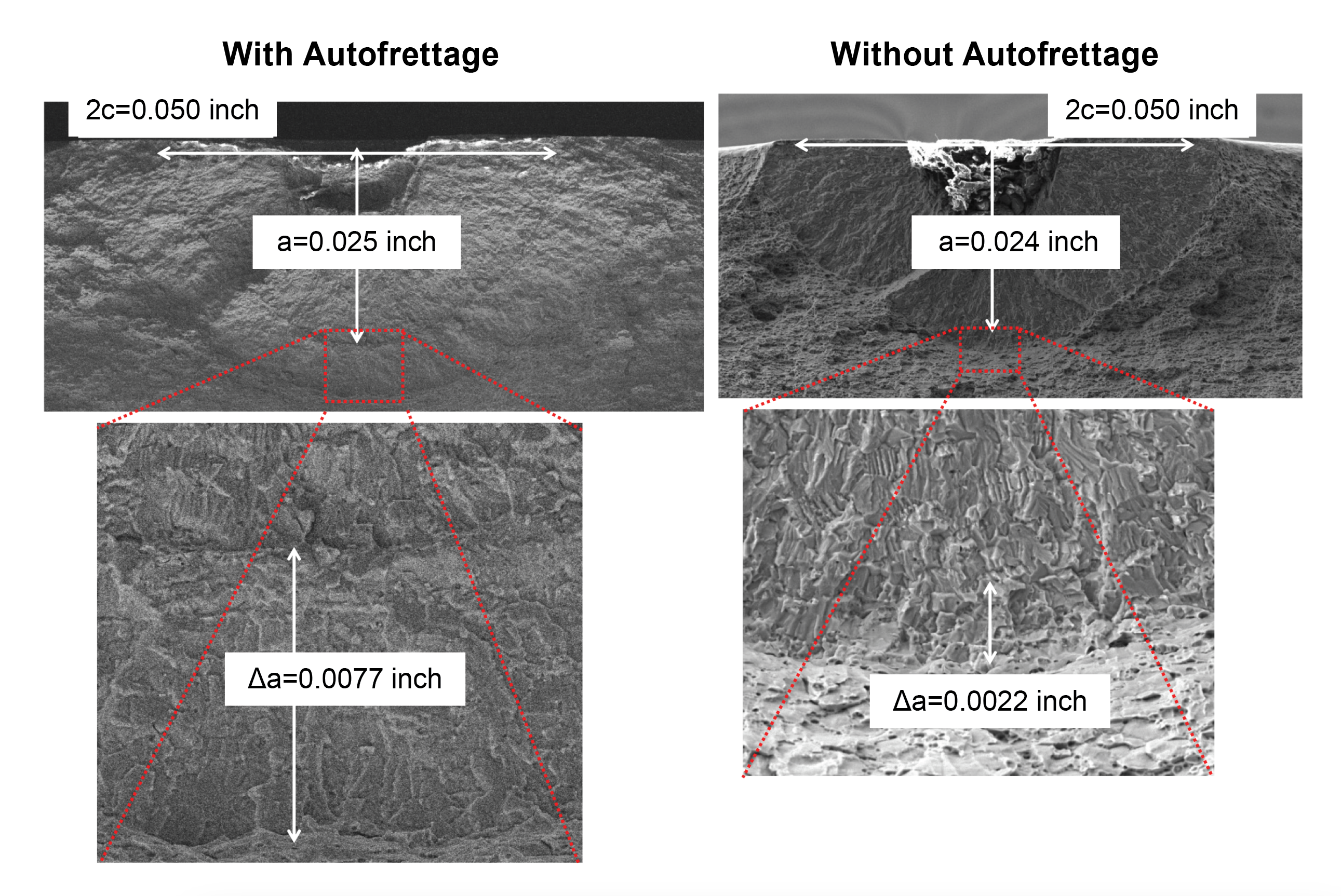

Figure 2. Fracture surfaces from two identical tests showing crack growth (Δa), with and without an initial autofrettage cycle. 

A validated finite element analysis and experimental measurements were used to evaluate the influence of the autofrettage cycle. The elastic-plastic autofrettage cycle was found to create a large region of plastic deformation ahead of the crack and blunted the crack tip. Previous fracture mechanics tests and analytical studies in the literature examined elastic overloads and found that plastic deformation ahead of the crack developed residual stresses that closed the crack surfaces, reducing the subsequent crack growth rate. However, the crack blunting allowed the crack to remain open for the entire loading, as illustrated by the finite element simulations of the crack surfaces at peak and minimum stress (Figure 3). The differences between the tests with and without the autofrettage cycle that were observed experimentally and simulated with a validated finite element analysis indicate that the damage tolerance analysis approach allowed by the standard can be unconservative. The NESC proposed an alternative damage tolerance analysis approach and recommended that the AIAA Aerospace Pressure Vessel Committee on standards update the ANSI/AIAA S-081B standard to address COPV liners with compressive stresses following the peak autofrettage stress.
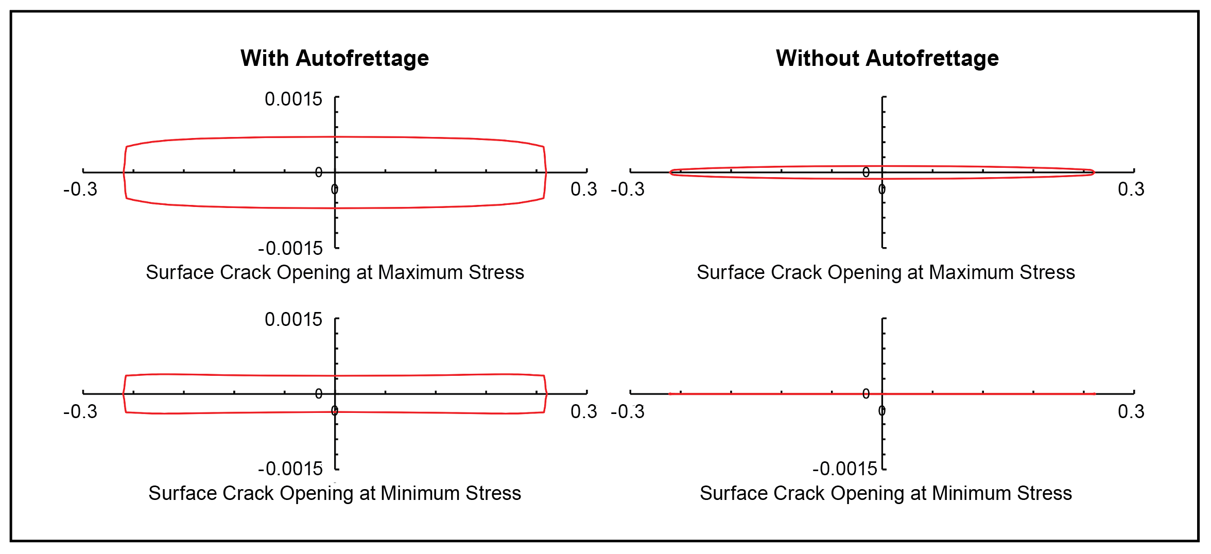
 
Figure 3. Abaqus finite element analysis of crack growth with and without an autofrettage cycle. Y-axis indicates crack opening displacement and x-axis indicates crack length.

A Brief Introduction to Damage Tolerance for COPVs 

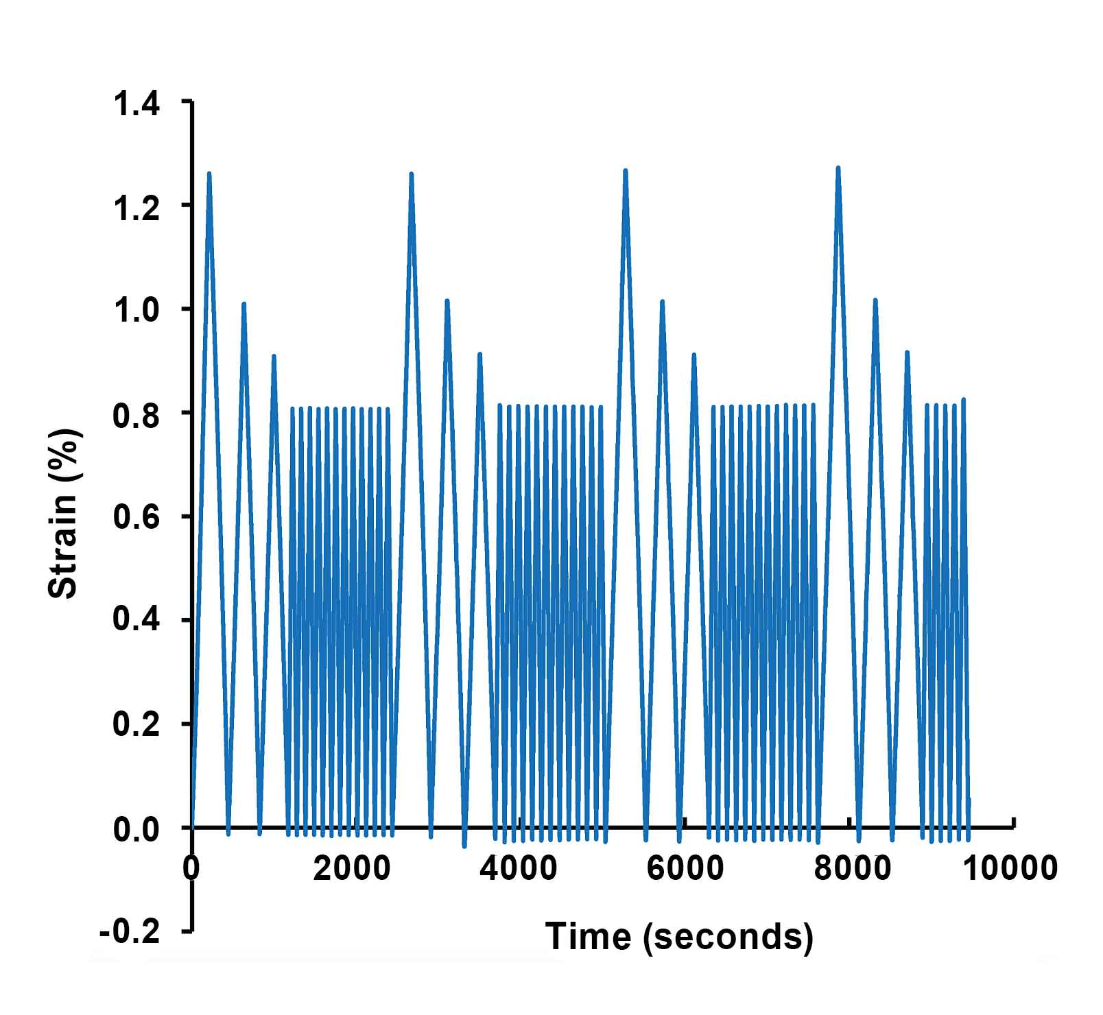
ANSI/AIAA S-081B standard, Space Systems–Composite Overwrapped Pressure Vessels, is a compilation of accepted practices for COPVs used in space applications developed as a collaboration of industry, government, and universities. The standard covers many aspects of COPVs including damage tolerance life analyses that are used for flight qualification overseen by fracture control boards. The standard for damage tolerance requires that the COPV “…survive four operational lifetimes with the largest crack in the metallic liner that can be missed by a nondestructive evaluation (NDE) subjected to bounding stresses representative of what the COPV experiences in its life (manufacturing, integration, operational including thermal and residual).” The operational life of a COPV liner typically includes an initial elastic-plastic cycle (autofrettage or proof) followed by other cycles that may be elastic (elastically responding liners) or elastic-plastic (plastically responding liners). A representative load spectrum is shown at right. During autofrettage, the COPV is pressurized to at least proof pressure to compress the liner inner surface, making it less susceptible to operational stresses. COPVs with elastically responding liners may be damage-tolerance qualified using LEFM analysis tools, but plastically responding liners must be damage-tolerance qualified by testing. Guidance on evaluating the appropriateness of LEFM tools for COPV damage tolerance was provided in NESC Technical Bulletin No. 21-04, Evaluating Appropriateness of LEFM Tools for COPV and Metal Pressure Vessel Damage Tolerance Life Verification Tolerance Life Verification and NASA/TM-2020-5006765/Volumes 1/2. 

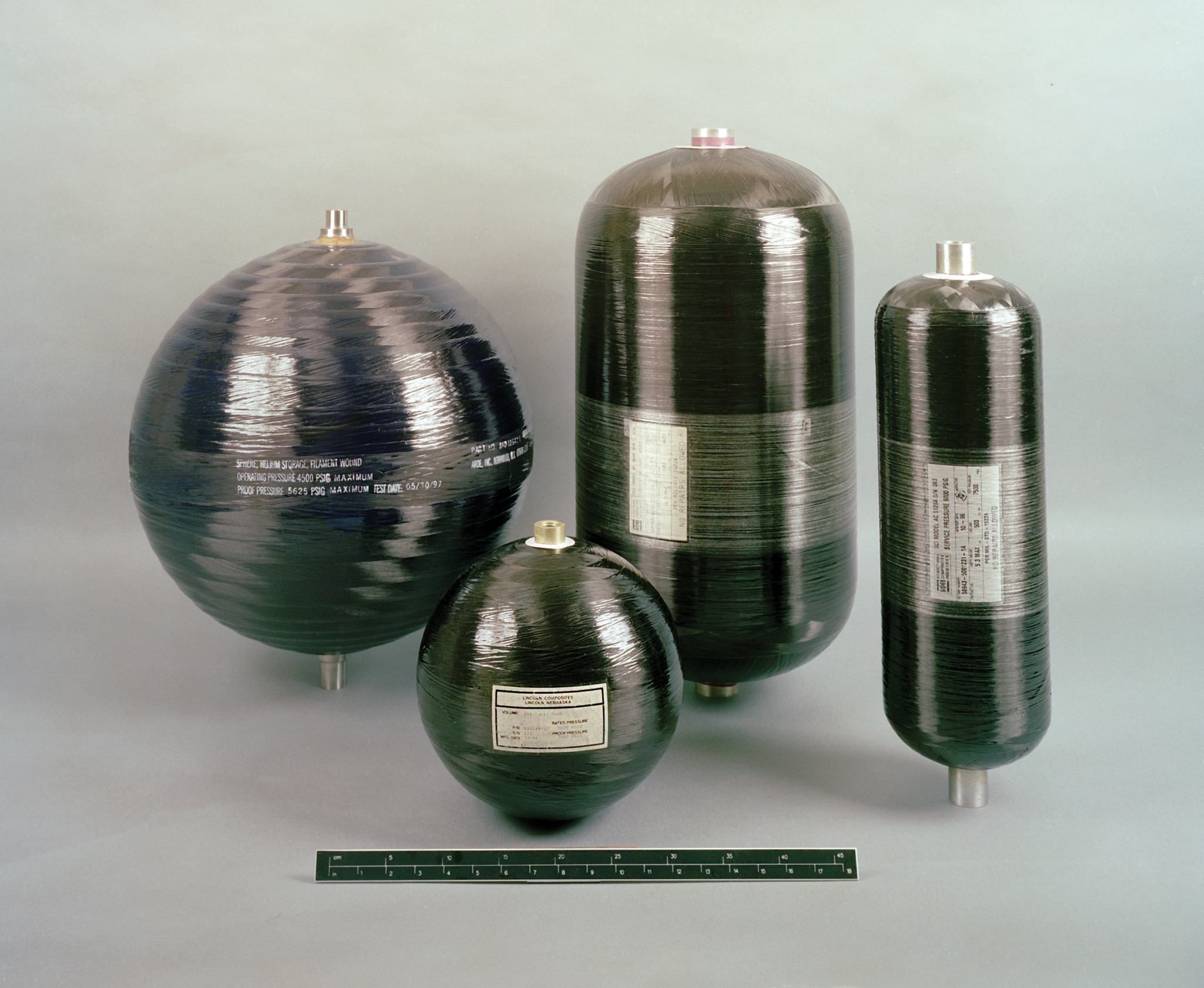
A COPV consists of a metallic liner with an exterior composite wrap. The composite provides strength, and the liner contains the compressed fluid or gas.
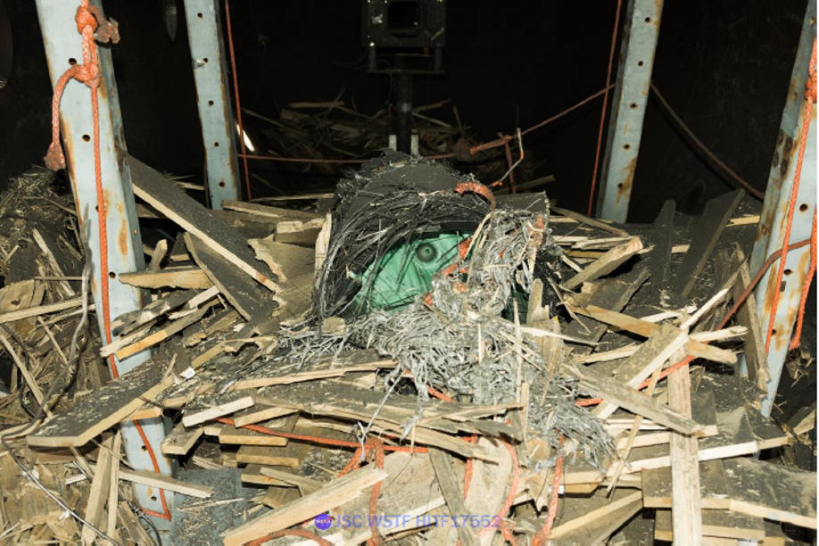
Results of a failure test. COPVs contain high pressure gases or fluids that can have tremendous explosive energy. 

Future of the Structures Discipline 

As the Agency moves more toward forming strategic industry partnerships with commercial contracts for new programs, the Structures TDT has highlighted the need for proper focus on appropriate requirements as the Team’s strategic vector. Although NASA Standards are often provided for reference, their prescriptive nature is not necessarily appropriate for use with commercial contracts. Industry partners and/or NASA team members create alternative standards, unique for each program, but there is inconsistency across different programs with respect to detailed requirements in these standards. Emerging technologies such as soft goods, large-scale deployable structures, inflatables, probabilistic analysis techniques, and additive manufactured hardware all drive unique requirements. The TDT identified the need for a tailoring guide, tied to mission priorities and risk postures, to assist with insight/oversight strategies for NASA programs. Using industry partners also means less NASA-owned hardware, which can lead to a loss of institutional knowledge. 

Representative loading spectrum for an elastically responding COPV liner with an initial elastic-plastic cycle.  

Its imperative that Engineering Directorates at each center proactively look for in-house projects so the next generation of engineers have opportunities for hands-on experience developing, designing, and testing (DDT) flight hardware. This experience is the foundation necessary for NASA engineers to guide the commercial partners through their own DDT processes and to be able to provide appropriate verification and validation of NASA requirements. Structures TDT members form a diverse team crossing all centers and programs, facilitating good collaboration on requirement interpretation, which ultimately ensures safety of NASA crew and mission success of operations in these new commercial programs. 

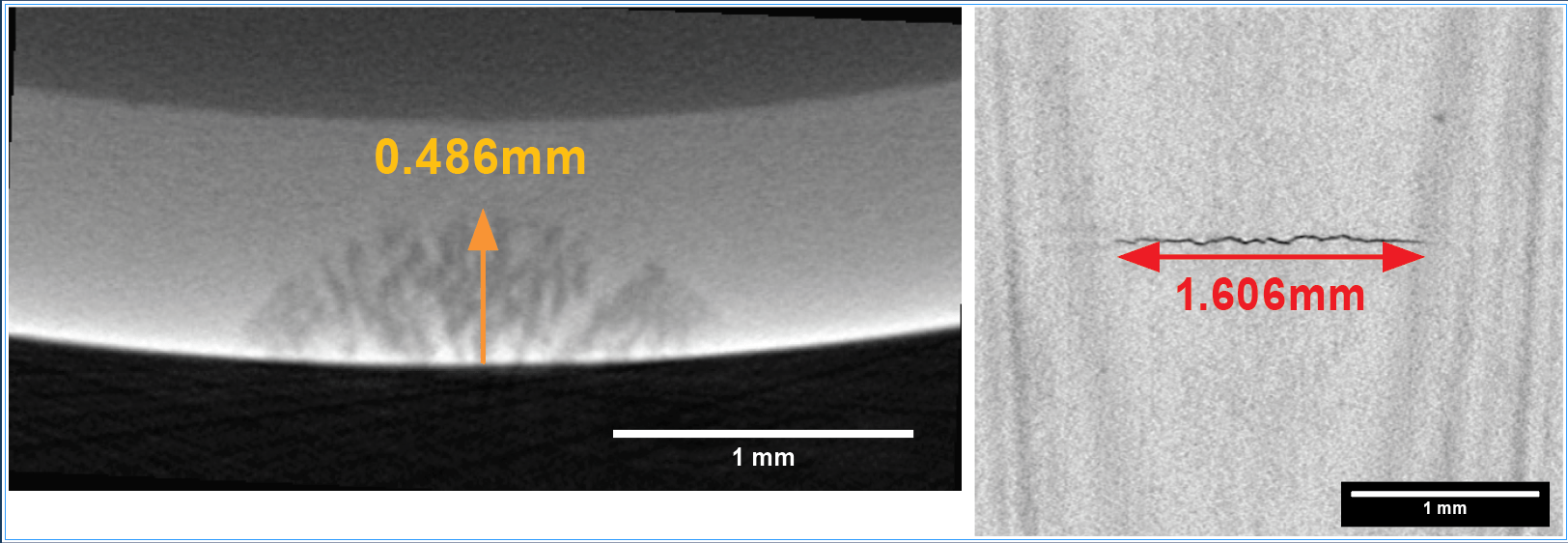
Computed tomography scan of a metallic liner detecting a part-through crack. 

Powered by WPeMatico

Get The Details…
Meagan Chappell