NASA Armstrong Builds Model Wing to Help Advance Unique Design

NASA Armstrong Builds Model Wing to Help Advance Unique Design

4 min read

Preparations for Next Moonwalk Simulations Underway (and Underwater)

Experimental Fabrication Shop technicians created parts for the assembly of a Transonic Truss-Braced Wing model. Based at NASA’s Armstrong Flight Research Center in Edwards, California, the technicians also assembled sections, and did a final fit-check to ensure the wing model was ready for testing.
Credits: NASA/Quincy Eggert

German Escobar works on a model aircraft wing structure that has two long sides and bars in between, which resembles a mini ladder. He sands the rough edges, uses four vices to secure it, and uses a milling machine he programmed to make precision holes.

Escobar is one of the Experimental Fabrication Shop technicians at NASA’s Armstrong Flight Research Center, Edwards California. The team made 29 different types of parts, more than 50 in total, to assemble a 10-foot unique wing model that will help calibrate fiber optic instrumentation and contribute data for a future wing model to show how the design improves fuel efficiency.

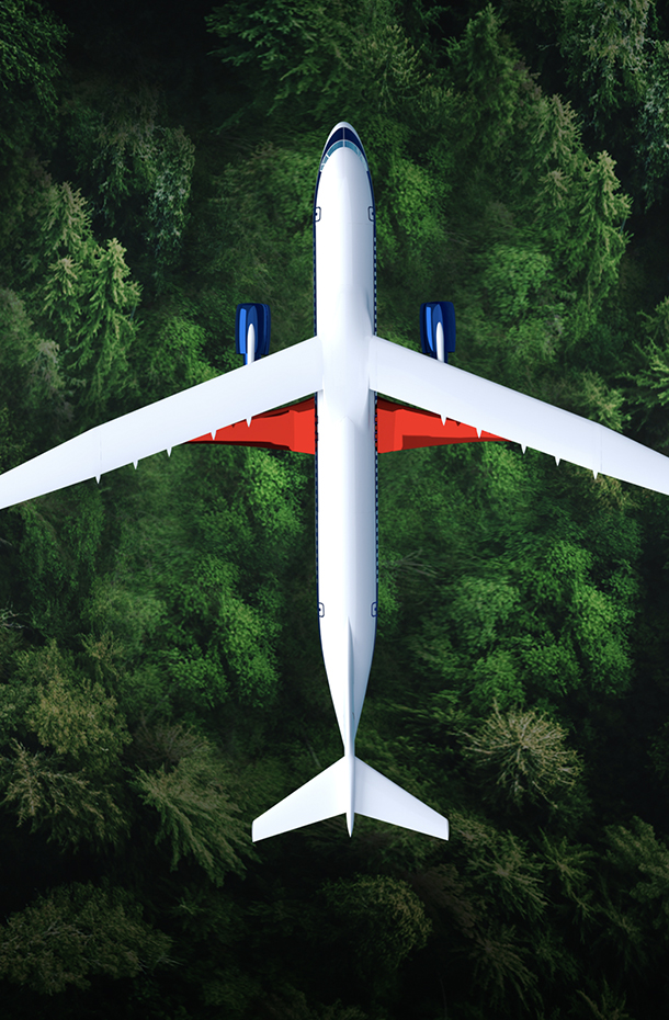
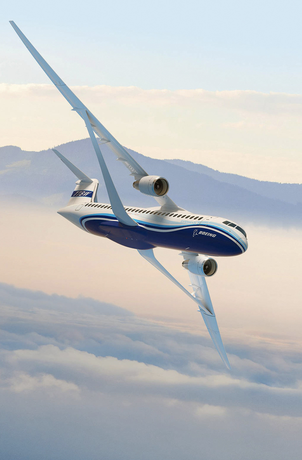
The experimental wing model has many features of the X-66 Transonic Truss-Braced Wing. The X-66 wing is braced on an aircraft using diagonal struts that also add lift and could result in significantly improved aerodynamics.

A man works on a machine to mill a key piece for a 10-foot wing model.
German Escobar works on milling the strut frame assembly for a 10-foot model of the Transonic Truss-Braced Wing at NASA’s Armstrong Flight Research Center in Edwards, California. The aircraft concept involves a wing braced on an aircraft using diagonal struts that also add lift and could result in significantly improved aerodynamics.
NASA/Steve Freeman

NASA Armstrong’s many capabilities enabled a start-to-finish design, fabrication, and soon testing of the 10-foot model wing. The Flight Loads Laboratory provided specifications for the model, including some of its own calculations from a 6-foot efficient wing test build at the center in Dec. 21, 2022. NASA’s Advanced Air Transportation Technology project funded the model wings.

In addition, NASA Armstrong and NASA’s Langley Research Center in Hampton, Virginia, are working on a proposal for 15-foot wing called the Structural Wing Experiment Evaluating Truss-Bracing. That wing would include ground vibration testing that would give a clearer picture of how it would react to different kinds of vibration in flight.  

Andrew Holguin, a design engineer, created 3D representations of the parts and how to assemble them. Holguin divided the model wing work into subassemblies to make it easier to focus on a single set of tasks. With the design fully approved and the task orders written, Escobar began his work.
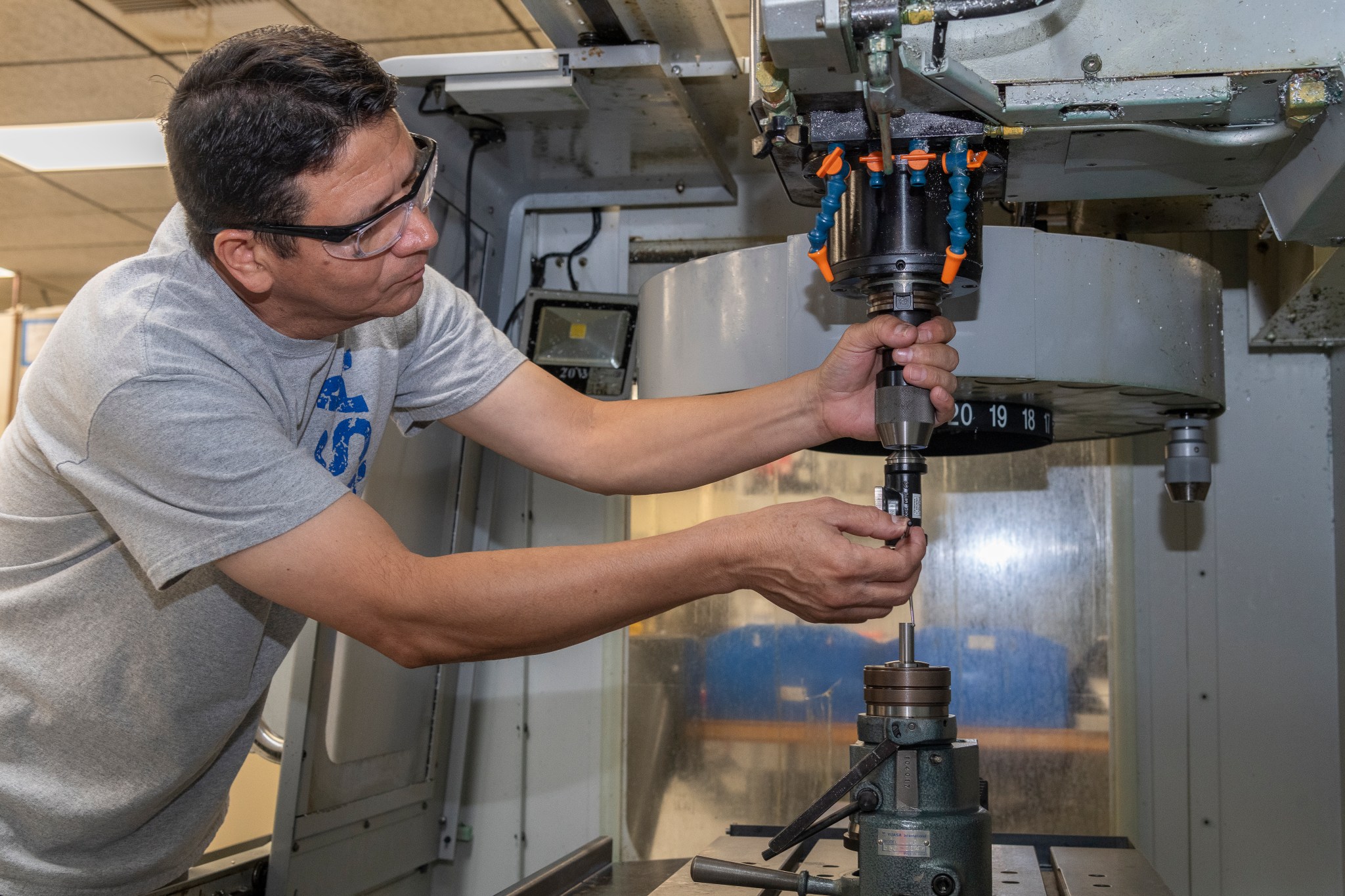
A man programs a machine to make a part for a 10-foot wing model.
Jose Vasquez programed a machine to cut, rotate and turn a block of steel to form a jury strut adaptor for a 10-foot model of the Transonic Truss-Braced Wing at NASA’s Armstrong Flight Research Center, in Edwards, California. The aircraft concept involves a wing braced on an aircraft using diagonal struts that also add lift and could result in significantly improved aerodynamics.
NASA/Steve Freeman

The ability to work items simultaneously is an advantage. Jose Vasquez, an engineering technician, used software to instruct a five-axis milling machine how to cut, rotate and transform a block of steel into an adapter. Water shoots at the cutting mechanism to keep everything from getting too hot.

Once the part was finished, Vasquez removed it from the machine cleaned it and used a pair of calipers, and a fine measurement tool called a micrometer, to check ensure the adaptor meets the wing model’s precise needs. If a calibration tool does not exist to check a specialized component, technicians can make one.

Elsewhere in the lab, sheet metal technician Matt Sanchez used a press brake to make bends in an aluminum sheet to form a rectangle called a wing rib. In another step he added hardware to the rib and later installed it in the model wing.
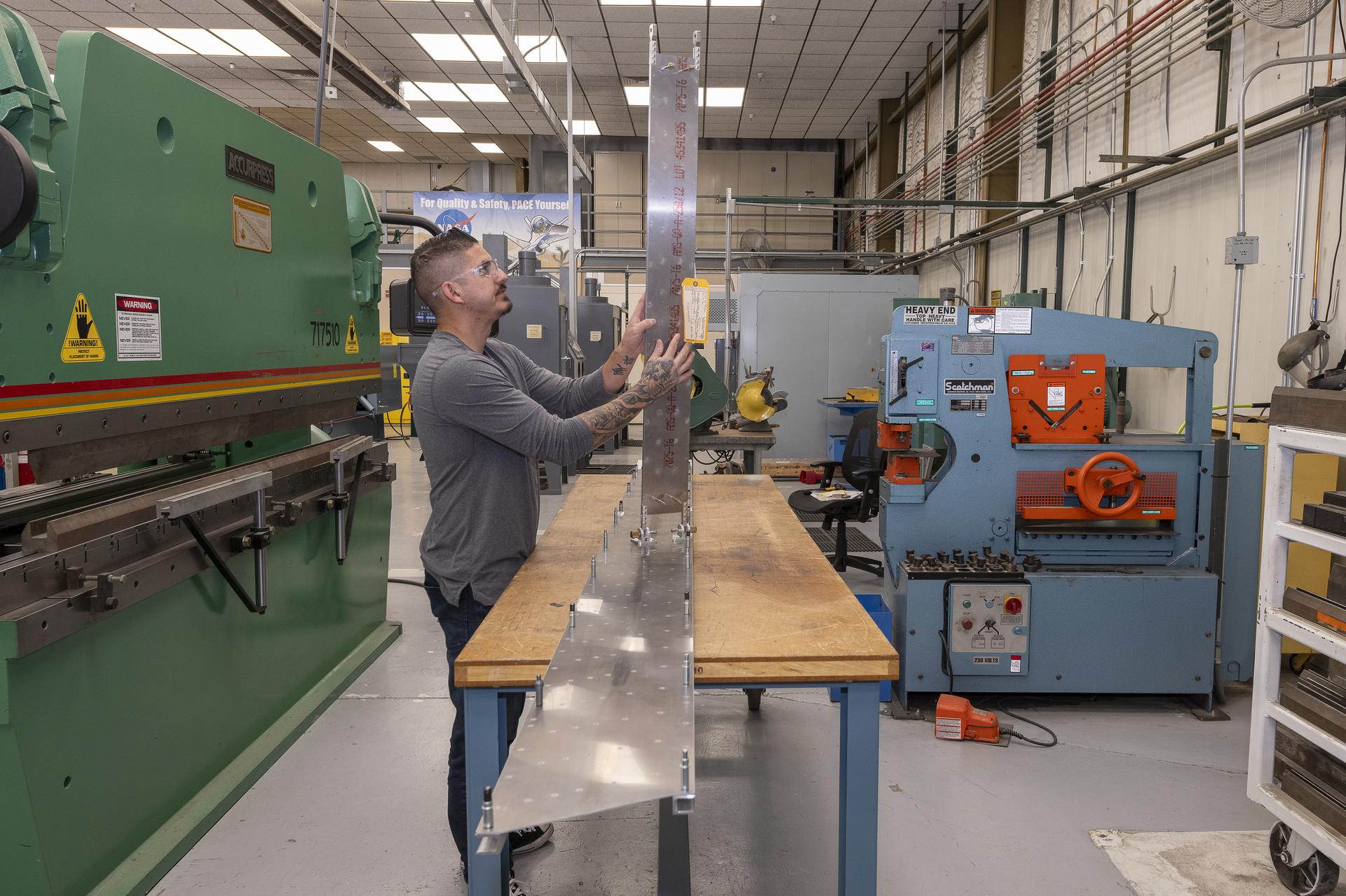
A man attaches components to assure they will fit together for testing of a 10-foot wing model.
Matthew Sanchez attaches the strut and the wing to ensure they fit together as intended for a 10-foot model of the Transonic Truss-Braced Wing at NASA’s Armstrong Flight Research Center in Edwards, California. The aircraft concept involves a wing braced on an aircraft using diagonal struts that also add lift and could result in significantly improved aerodynamics.
NASA/Genaro Vavuris

As the assembly was nearly complete, an outer wing cover was required. Sanchez set up the drawings, placed a sheet of aluminum into the water jet table and started it. Under the water the saw moved quickly to cut the strut covering down, around, and up the other side, and stopping with the complete cut. Sanchez took the piece from the table and dried it.

To wrap up this part of the work, he did a successful check of all the components called a fit check. With the wing model complete, the Flight Loads Laboratory staff continues to complete design and preparations to build a fixture for the wing tests. The fixture will join the experimental wing model, test instrumentation, and enable tests that can contribute to the next aviation innovation.

Here is a gallery of the building of the parts and the wing.

Powered by WPeMatico

Get The Details…
Dede Dinius
NASA Telescopes Chase Down “Green Monster” in Star’s Debris

NASA Telescopes Chase Down “Green Monster” in Star’s Debris

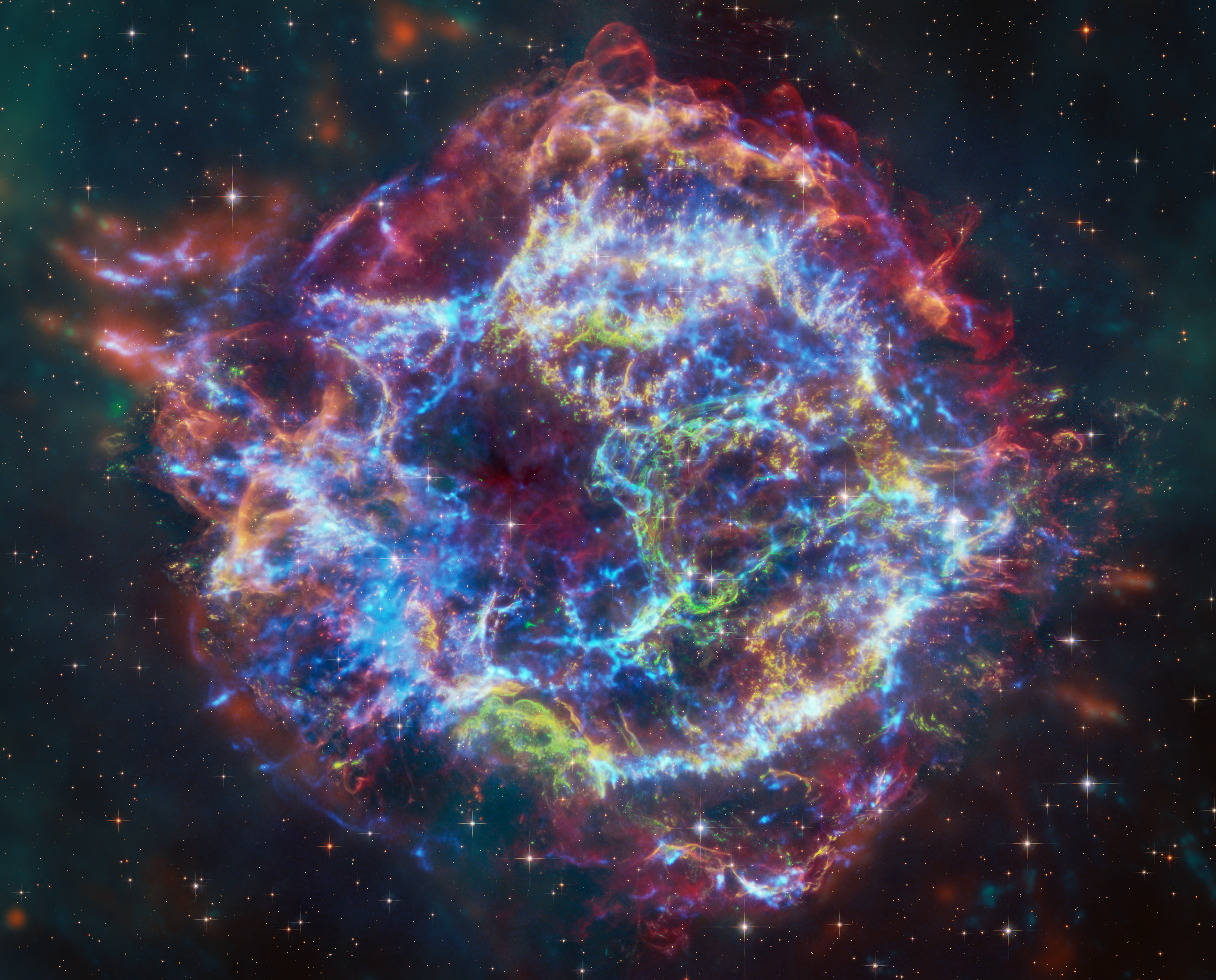
For the first time astronomers have combined data from NASA’s Chandra X-ray Observatory and James Webb Space Telescope to study the well-known supernova remnant Cassiopeia A (Cas A). As described in our latest press release, this work has helped explain an unusual structure in the debris from the destroyed star called the “Green Monster”, first discovered in Webb data in April 2023. The research has also uncovered new details about the explosion that created Cas A about 340 years ago, from Earth’s perspective.

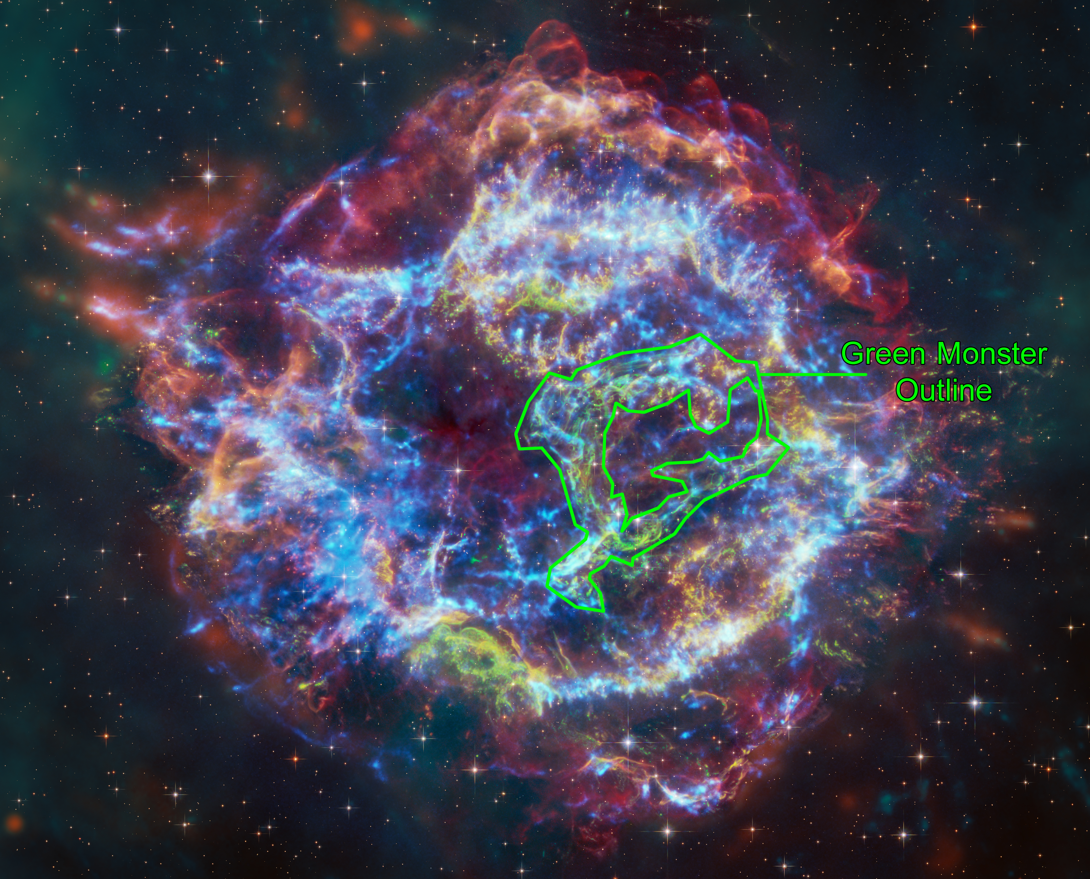
A new composite image contains X-rays from Chandra (blue), infrared data from Webb (red, green, blue), and optical data from Hubble (red and white). The outer parts of the image also include infrared data from NASA’s Spitzer Space Telescope (red, green and blue). The outline of the Green Monster can be seen in the second image of the carousel.

The Chandra data reveals hot gas, mostly from supernova debris from the destroyed star, including elements like silicon and iron. In the outer parts of Cas A the expanding blast wave is striking surrounding gas that was ejected by the star before the explosion. The X-rays are produced by energetic electrons spiraling around magnetic field lines in the blast wave. These electrons light up as thin arcs in the outer regions of Cas A, and in parts of the interior. Webb highlights infrared emission from dust that is warmed up because it is embedded in the hot gas seen by Chandra, and from much cooler supernova debris. The Hubble data shows stars in the field.

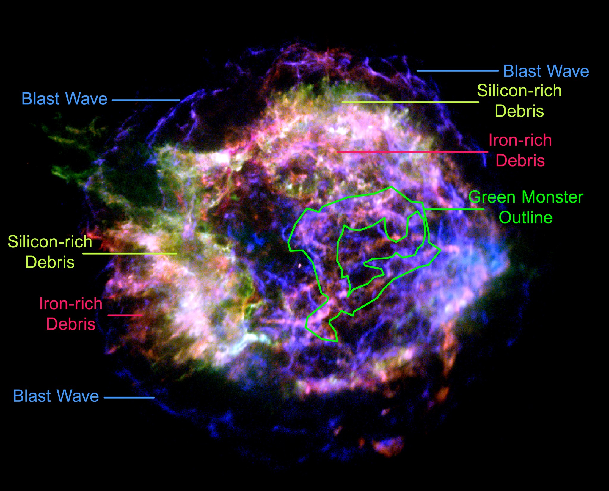
A separate graphic shows a color Chandra image, where red shows iron and magnesium at low X-ray energies, green shows silicon at intermediate X-ray energies and blue shows the highest energy X-rays, from electrons spiraling around magnetic field lines. An outline of the Green Monster, plus the locations of the blast wave, and of debris rich in silicon and iron are labeled.

Chandra Image of Cassiopeia A, Labeled
Credit: NASA/CXC/SAO

Detailed analysis by the researchers found that filaments in the outer part of Cas A, from the blast wave, closely matched the X-ray properties of the Green Monster, including less iron and silicon than in the supernova debris. This interpretation is apparent from the color Chandra image, which shows that the colors inside the Green Monster’s outline best match with the colors of the blast wave rather than the debris with iron and silicon. The authors conclude that the Green Monster was created by a blast wave from the exploded star slamming into material surrounding it, supporting earlier suggestions from the Webb data alone.

The debris from the explosion is seen by Chandra because it is heated to tens of millions of degrees by shock waves, akin to sonic booms from a supersonic plane. Webb can see some material that has not been affected by shock waves, what can be called “pristine” debris.

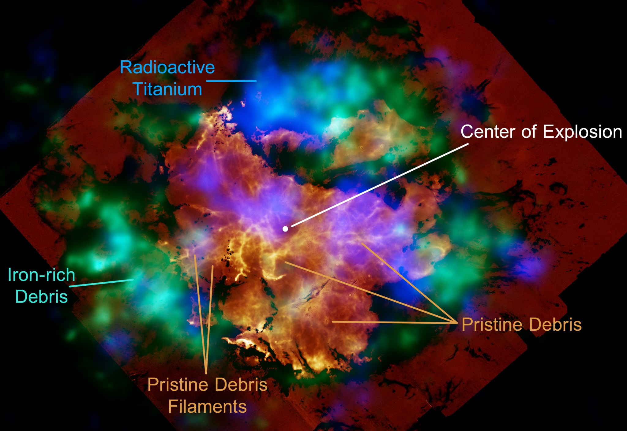
To learn more about the supernova explosion, the team compared the Webb view of the pristine debris with X-ray maps of radioactive elements that were created in the supernova. They used NASA’s Nuclear Spectroscopic Telescope Array (NuSTAR) data to map radioactive titanium — still visible today — and Chandra to map where radioactive nickel was by measuring the locations of iron. Radioactive nickel decays to form iron. An additional image shows the iron-rich debris (tracing where radioactive nickel was located) in green, the radioactive titanium in blue and the pristine debris seen in orange and yellow.

Iron/Titanium/Pristine Debris Cassiopeia A, Labeled
Credit: NASA/CXC/SAO

Some filaments of pristine debris near the center of Cas A, seen with Webb, are connected to the iron seen with Chandra farther out. Radioactive titanium is seen where pristine debris is relatively weak.

These comparisons suggest that radioactive material seen in X-rays has helped shape the pristine debris near the center of the remnant seen with Webb, forming cavities. The fine structures in the pristine debris were most likely formed when the star’s inner layers were violently mixed with hot, radioactive matter produced during collapse of the star’s core under gravity.

These results were presented by Dan Milisavljevic from Purdue University at the 243rd meeting of the American Astronomical Society in New Orleans. They are described in more detail in two papers submitted to Astrophysical Journal Letters, one led by Milisavljevic focused on the Webb results (preprint here) and the other led by Jacco Vink of the University of Amsterdam focused on the Chandra results (preprint here). The co-authors of Vink’s paper are Manan Agarwal (University of Amsterdam, the Netherlands), Patrick Slane (Center for Astrophysics | Harvard & Smithsonian – CfA), Ilse De Looze (Ghent University, Belgium), Dan Milisavljevic, Daniel Patnaude (CfA), Paul Plucinsky (CfA), and Tea Temin (Princeton University). Related papers by other members of the research team are also in preparation.

The Smithsonian Astrophysical Observatory’s Chandra X-ray Center controls science operations from Cambridge, Massachusetts, and flight operations from Burlington, Massachusetts.

The James Webb Space Telescope is the world’s premier space science observatory. Webb is solving mysteries in our solar system, looking beyond to distant worlds around other stars, and probing the mysterious structures and origins of our universe and our place in it. Webb is an international program led by NASA with its partners, ESA (European Space Agency) and the Canadian Space Agency.

A Small Explorer mission led by Caltech and managed by JPL for NASA’s Science Mission Directorate in Washington, NuSTAR was developed in partnership with the Danish Technical University and the Italian Space Agency (ASI). The spacecraft was built by Orbital Sciences Corp. in Dulles, Virginia. NuSTAR’s mission operations center is at the University of California, Berkeley, and the official data archive is at NASA’s High Energy Astrophysics Science Archive Research Center at the agency’s Goddard Space Flight Center in Greenbelt, Maryland. ASI provides the mission’s ground station and a mirror data archive. Caltech manages JPL for NASA.

Read more from NASA’s Chandra X-ray Observatory.

For more Chandra images, multimedia and related materials, visit:

https://www.nasa.gov/mission/chandra-x-ray-observatory/

Visual Description:

This image of Cassiopeia A resembles a disk of electric light with red clouds, glowing white streaks, red and orange flames, and an area near the center of the remnant resembling a somewhat circular region of green lightning. X-rays from Chandra are blue and reveal hot gas, mostly from supernova debris from the destroyed star, and include elements like silicon and iron. X-rays are also present as thin arcs in the outer regions of the remnant.

Infrared data from Webb is red, green, and blue. Webb highlights infrared emission from dust that is warmed up because it is embedded in the hot gas seen by Chandra, and from much cooler supernova debris. Hubble data shows a multitude of stars that permeate the field of view.

News Media Contact

Megan Watzke
Chandra X-ray Center
Cambridge, Mass.
617-496-7998

Jonathan Deal
Marshall Space Flight Center
Huntsville, Ala.
256-544-0034

Powered by WPeMatico

Get The Details…
Lee Mohon

NASA Science Heads to Moon on First US Private Robotic Artemis Flight 

NASA Science Heads to Moon on First US Private Robotic Artemis Flight 

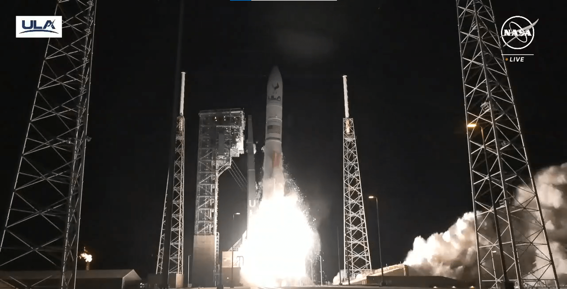
As part of NASA’s Commercial Lunar Payload Services initiative, Astrobotic’s Peregrine lander launched on United Launch Alliance’s (ULA) Vulcan rocket at 2:18 a.m. EST from Launch Complex 41 at Cape Canaveral Space Force Station in Florida.

Carrying NASA scientific instruments as part of its Commercial Lunar Payload Services initiative, Astrobotic’s Peregrine lander launched on United Launch Alliance’s (ULA) Vulcan rocket at 2:18 a.m. EST from Launch Complex 41 at Cape Canaveral Space Force Station in Florida. Peregrine has about a 46-day journey to reach the lunar surface.

Once on the Moon, NASA instruments will study the lunar exosphere, thermal properties of the lunar regolith, hydrogen abundances in the soil at the landing site, and conduct radiation environment monitoring. The five NASA science and research payloads aboard the lander will help the agency better understand planetary processes and evolution, search for evidence of water and other resources, and support long-term, sustainable human exploration.

“The first CLPS launch has sent payloads on their way to the Moon – a giant leap for humanity as we prepare to return to the lunar surface for the first time in over half a century,” said NASA Administrator Bill Nelson. “These high-risk missions will not only conduct new science at the Moon, but they are supporting a growing commercial space economy while showing the strength of American technology and innovation. We have so much science to learn through CLPS missions that will help us better understand the evolution of our solar system and shape the future of human exploration for the Artemis Generation.”  

For this CLPS flight, NASA research includes:

  • Laser Retroreflector Array: A collection of approximately half-inch (1.25 cm.) retro-reflectors – a mirror used for measuring distance – mounted to the lander. This mirror reflects laser light from other orbiting and landing spacecrafts to precisely determine the lander’s position.
  • Neutron Spectrometer System: This system will search for indicators of water near the lunar surface by detecting the presence of hydrogen-bearing materials at the landing site as well as determining bulk properties of the regolith there.
  • Linear Energy Transfer Spectrometer: This radiation sensor will collect information about the lunar radiation environment and any solar events that might occur during the mission. The instrument relies on flight-proven hardware that flew in space on the Orion spacecraft’s inaugural uncrewed flight in 2014.
  • Near InfraRed Volatiles Spectrometer System: This system will measure surface hydration and volatiles. It will also detect certain minerals using spectroscopy while mapping surface temperature and changes at the landing site.
  • Peregrine Ion-Trap Mass Spectrometer: This instrument will study the thin layer of gases on the Moon’s surface, called the lunar exosphere, and any gases present after descent and landing and throughout the lunar day to understand the release and movement of volatiles. It was previously developed for ESA’s (European Space Agency) Rosetta mission.  

Peregrine is scheduled to land on the Moon on Friday, Feb. 23, and will spend approximately 10 days gathering valuable scientific data studying Earth’s nearest neighbor and helping pave the way for the first woman and first person of color to explore the Moon under Artemis.

Learn more about NASA’s CLPS initiative at:

https://www.nasa.gov/clps

-end-

Karen Fox / Alise Fisher
Headquarters, Washington
202-358-1600 / 202-358-2546
karen.fox@nasa.gov / alise.m.fisher@nasa.gov   

Nilufar Ramji
Johnson Space Center, Houston
281-483-5111
nilufar.ramji@nasa.gov

Antonia Jaramillo
Kennedy Space Center, Florida
321-501-8425
antonia.jaramillobotero@nasa.gov

Share

Details

Last Updated

Jan 08, 2024

Powered by WPeMatico

Get The Details…
Abbey A. Donaldson

NASA, United Arab Emirates Announce Artemis Lunar Gateway Airlock

NASA, United Arab Emirates Announce Artemis Lunar Gateway Airlock

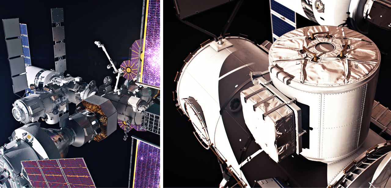
NASA and the Mohammed Bin Rashid Space Centre (MBRSC) have entered into an agreement for MBRSC to provide the Crew and Science Airlock module for the Gateway Space Station. As part of the agreement, NASA will fly a United Arab Emirates astronaut to Gateway on a future Artemis mission. Pictured is an artist’s concept of Gateway (left) and an artist’s concept of a government reference airlock (right).
NASA

NASA and the Mohammed bin Rashid Space Centre (MBRSC) of the United Arab Emirates (UAE) announced Sunday plans for the space centre to provide an airlock for Gateway, humanity’s first space station that will orbit the Moon. The lunar space station will support NASA’s missions for long-term exploration of the Moon under Artemis for the benefit of all.

“As chair of the National Space Council, I have made it a priority to enhance international cooperation in space. Today’s announcement and partnership between the United States and United Arab Emirates advances this important work. By combining our resources, scientific capacity, and technical skill, the U.S. and UAE will further our collective vision for space and ensure it presents extraordinary opportunities for everyone here on Earth,” said Vice President Kamala Harris.

Under a new implementing arrangement expanding their human spaceflight collaboration with NASA through Gateway, MBRSC will provide Gateway’s Crew and Science Airlock module, as well as a UAE astronaut to fly to the lunar space station on a future Artemis mission.

“The United States and the United Arab Emirates are marking a historic moment in our nations’ collaboration in space, and the future of human space exploration,” said NASA Administrator Bill Nelson. “We are in a new era of exploration through Artemis – strengthened by the peaceful and international exploration of space. The UAE’s provision of the airlock to Gateway will allow astronauts to conduct groundbreaking science in deep space and prepare to one day send humanity to Mars.”

In addition to operating the airlock, MBRSC also will provide engineering support for the life of the lunar space station. The airlock will allow crew and science research transfers to and from the habitable environment of Gateway’s pressurized crew modules to the vacuum of space. These transfers will support broader science in the deep space environment, as well as Gateway maintenance.

Gateway will support sustained exploration and research in deep space, provide a home for astronauts to live and work, including a staging point for lunar surface missions, and an opportunity to conduct spacewalks while orbiting the Moon.

NASA’s Artemis program is the most diverse and broad coalition of nations in human exploration in deep space. In collaboration with the CSA (Canadian Space Agency), ESA (European Space Agency), JAXA (Japan Aerospace Exploration Agency), and now the MBRSC, NASA will return humans to the lunar surface for scientific discovery and chart a path for the first human missions to Mars.

This latest cooperation on Gateway builds on NASA’s and UAE’s previous human spaceflight collaboration. In 2019, Hazzaa Almansoori became the first Emirati to fly to space during a short mission to the International Space Station, in which he collaborated with NASA to perform experiments and educational outreach. A second Emirati astronaut, Sultan Al Neyadi, launched to the space station in 2023 on NASA’s SpaceX Crew-6 mission, where he participated in the floating laboratory’s scientific research that advances human knowledge and improves life on Earth. The UAE currently has two additional astronaut candidates in training at NASA’s Johnson Space Center in Houston. NASA has also worked with UAE on Mars research and human research and analog studies to support mutual exploration priorities.

In 2020, the United States and UAE were among the original signers of the Artemis Accords, which are a practical set of principles to guide space exploration cooperation among nations participating in NASA’s 21st century lunar exploration program.

Through Artemis, NASA will land the first woman and the first person of color on the surface of the Moon, paving the way for a long-term lunar presence and serving as a steppingstone to send the first astronauts to Mars. 

https://www.nasa.gov/artemis

-end-

Vanessa Lloyd / Kathryn Hambleton
Headquarters, Washington
202-358-1600
vanessa.c.lloyd@nasa.gov / kathryn.hambleton@nasa.gov

Dylan Connell
Johnson Space Center, Houston
281-483-5111
dylan.b.connell@nasa.gov

Share

Details

Last Updated

Jan 07, 2024

Powered by WPeMatico

Get The Details…
Abbey A. Donaldson

NASA Administrator, Leaders to Discuss Artemis Moon Mission Plans

NASA Administrator, Leaders to Discuss Artemis Moon Mission Plans

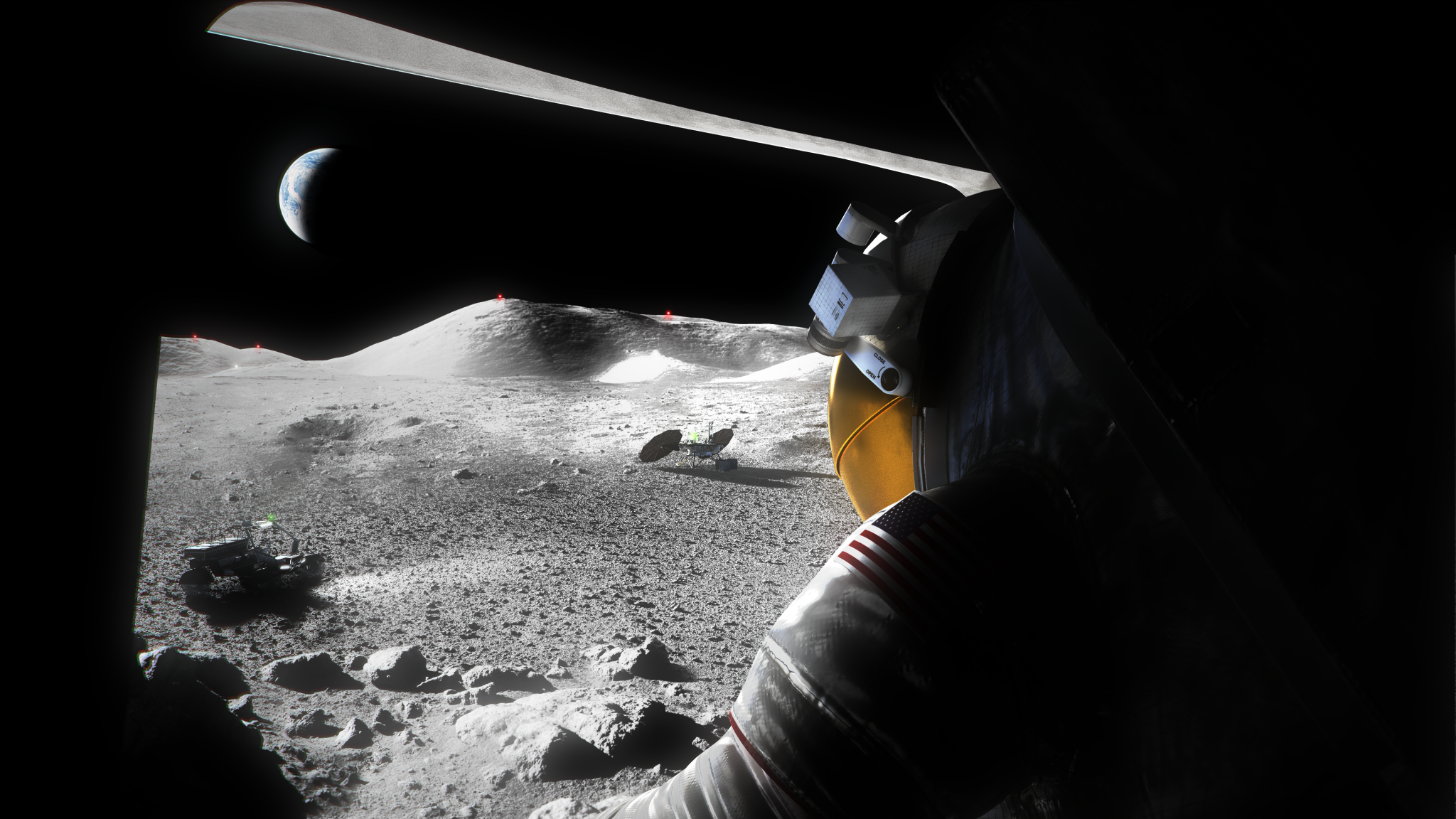
An illustration of a suited Artemis astronaut looking out of a Moon lander hatch across the lunar surface, the Lunar Terrain Vehicle and other surface elements.

NASA will hold a media teleconference at 1:30 p.m. EST Tuesday, Jan. 9, to provide an update on the agency’s lunar exploration plans for the benefit of all under Artemis.

Audio of the briefing will stream live on NASA’s website.

In addition to NASA Administrator Bill Nelson, agency participants will include:

  • NASA Associate Administrator Jim Free
  • Catherine Koerner, associate administrator, Exploration Systems Development Mission Directorate
  • Amit Kshatriya, deputy associate administrator, Moon to Mars Program, Exploration Systems Development Mission Directorate

Industry partner representatives also will be available to answer questions during the call.

To participate by telephone, media must RSVP no later than two hours prior to the start of the event to: kathryn.hambleton@nasa.gov. A copy of NASA’s media accreditation policy is online.

In the time since NASA’s successful flight test of the Artemis I mission, the agency has continued to learn from that flight and prepare for Artemis II, the first crewed mission around the Moon under Artemis. NASA has made significant progress toward Artemis III, which is planned to land the first astronauts near the lunar South Pole; Artemis IV, which is planned to be the first mission to incorporate the Gateway lunar space station; and future Artemis missions. The agency is closer than ever to once again exploring Earth’s nearest neighbor with astronauts for the benefit of humanity. 

Through Artemis, the agency will establish a long-term presence at the Moon for scientific exploration with our commercial and international partners, learn how to live and work away from home, and prepare for future human exploration of the Red Planet. The SLS (Space Launch System), exploration ground systems, and NASA’s Orion spacecraft, along with the human landing system, next-generation spacesuits, the lunar space station, Gateway, and future rovers are NASA’s foundation for deep space exploration.

For more information about Artemis, visit:

https://www.nasa.gov/artemis

-end-

Faith McKie / Kathryn Hambleton
Headquarters, Washington
202-358-1100
faith.d.mckie@nasa.gov / kathryn.hambleton@nasa.gov

Powered by WPeMatico

Get The Details…
Abbey A. Donaldson