NASA Administrator Names New Stennis Space Center Director

NASA Administrator Names New Stennis Space Center Director

John Bailey, wearing a dark suit and striped tie, sits for a portrait with the United State of American and NASA flags in the background
John Bailey, director, John C. Stennis Space Center

NASA Administrator Bill Nelson on Monday named John Bailey as director of the agency’s Stennis Space Center near Bay St. Louis, Mississippi, effective immediately. Bailey had been serving as acting director since January. 

“John will build on his nearly 35 years of federal service to lead our talented workforce at Stennis,” said Nelson. “So much of NASA runs through Stennis. It is where we hone new and exciting capabilities in aerospace, technology, and deep space exploration. I am confident that John will lead the nation’s largest and premier propulsion test site to even greater success.”

NASA Stennis also is a unique federal city, home to more than 50 resident tenants with a combined workforce of over 5,200. The center tested the SLS (Space Launch System) core stage that helped launch the Artemis I mission. It also is testing all RS-25 engines to help power SLS launches and will conduct flightworthy testing of the agency’s new exploration upper stage prior to its use in space on future Artemis missions to the Moon and beyond.

The center is a leader in partnering and working with commercial aerospace companies to support their propulsion test projects. It also is expanding as an aerospace and technology hub, and in development of intelligent and autonomous systems needed for deep space exploration.

“This is an exciting time for NASA Stennis, and I am deeply honored to lead its great family of employees who make up this amazing workforce,” Bailey said. “We are dedicated to continuing to provide frontline support to the agency’s missions and initiatives. I look forward to our shared future and success.”

Bailey has more than three decades of federal service with the U.S. Air Force and NASA. As a communications engineer with the U.S. Air Force, Bailey led electronic communications testing worldwide. He joined the NASA Stennis team in 1999 and subsequently served in a variety of roles, managing and leading technical and non-technical organizations and supervising employees with a wide range of skills and backgrounds.

Bailey was tapped in 2015 to lead the NASA Stennis Engineering and Test Directorate, managing critical rocket propulsion test assets exceeding $2 billion in value and projects more than $221 million. He was named NASA Stennis associate director in 2018 and selected as the center’s deputy director in 2021.

An Alabama native, Bailey holds a bachelor’s degree in Electrical Engineering and a master’s degree in Business Administration from the University of South Alabama.

Access Bailey’s online biography at:

https://www.nasa.gov/people/john-w-bailey-jr/

-end-

Cheryl Warner 
Headquarters, Washington 
202-358-1600 
cheryl.m.warner@nasa.gov

C. Lacy Thompson
Stennis Space Center, Bay St. Louis, Miss.
228-363-5499
calvin.l.thompson@nasa.gov

Powered by WPeMatico

Get The Details…
Abbey A. Donaldson

Major Martian Milestones

Major Martian Milestones

1 Min Read

Major Martian Milestones

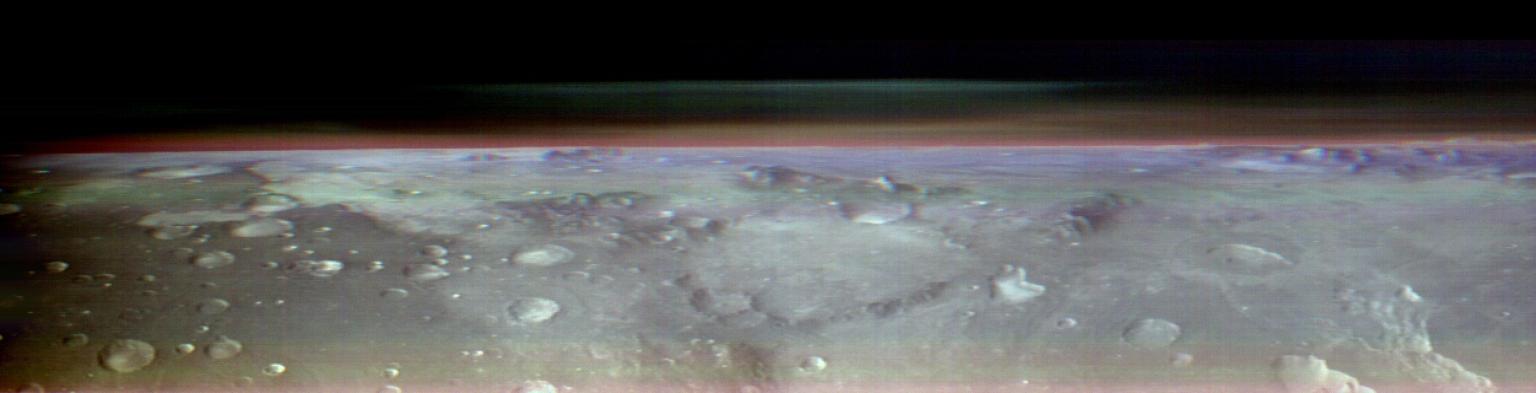
Water-ice (blue) and dust (red) in the atmosphere of Mars above the cratered Martian surface as viewed from orbit by the THEMIS camera (false-color composite image).

The horizon of Mars showing water-ice and dust in the atmosphere, as seen by the NASA’s Mars Odyssey mission on May 9, 2023. To find layers of ice and dust like these in Mars’s atmosphere, participants in the Cloudspotting on Mars project analyze data from a different infrared instrument, the Mars Climate Sounder on the Mars Reconnaissance Orbiter. More information on this image (including an animation) can be found here: https://mars.nasa.gov/resources/27816/odysseys-themis-views-the-horizon-of-mars/?site=msl.

There’s good news from NASA’s Cloudspotting on Mars project! That’s the project that invites you to help identify exotic clouds high in the Martian atmosphere.

  • Thanks to your help, the Cloudspotting on Mars project reached ahuge milestone. Another full Mars year, Mars Year 30 (Oct 2009 – Sep 2011), has been completed! That’s the second full Mars year of observations that has been analyzed since the project began. 
  • A new project from the Cloudspotting on Mars team has started its beta testing phase! In this new project, you’ll pick out cloud shapes in data from NASA’s Mars Atmosphere and Volatile Evolution (MAVEN) Mission.  If you’re willing to help beta test this project and provide feedback before it launches, please send an email to the team. We’ll let everyone know when this project officially launches, of course!

Congratulations to the Cloudspotting on Mars team and all the volunteers who have helped spot Martian clouds!

Powered by WPeMatico

Get The Details…

Innovation that Impacts All NASA Missions: Improving How We Engineer Our Systems

Innovation that Impacts All NASA Missions: Improving How We Engineer Our Systems

Download PDF: Innovation that Impacts All NASA Missions: Improving How We Engineer Our Systems

John F. Kennedy set the tone for NASA’s culture in 1961 during his famous speech on going to the Moon, “We choose to go to the Moon not because it’s easy, but because it’s hard; because that goal will serve to organize and measure the best of our energies and skills, because that challenge is one that we are willing to accept, one we are unwilling to postpone…”  

 That culture has never faded, even across NASA’s diverse spectrum of missions. The continuous challenge to do what is hard or near impossible includes the requirement for innovation. Innovation is the importance of what we do, but also how we do it. With a goal of improving the way NASA’s workforce engineers its systems, the Systems Engineering (SE) Technical Discipline Team (TDT) has partnered with numerous facets of the NASA workforce to better enable innovation in how we work. Over the past year, three diverse teams made progress toward that goal by looking at the way we levy technical standards, improving understanding and integrated risk (cost, schedule, and technical), reducing project risk by better management of mass growth, and moving SE into the model based digital domain. A brief summary of each team’s efforts follows. 
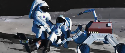
a). MBSE is being applied to help architect the ExMC, which is pushing the boundary of space medical systems to care for future astronauts. b). A proposed Mars sample return mission development project would benefit from using the NASA-endorsed ANSI/AIAA standard: Mass Properties Control for Space Systems

ExMC: Systems Analysis and Integration Using MBSE 

Via its Model-Based Systems Engineering (MBSE) Infusion And Modernization Initiative (MIAMI), the NESC SE TDT partnered with the Human Research Program’s Exploration Medical Capability (ExMC) Element (https://www.nasa.gov/hrp/elements/exmc) at JSC. ExMC has adopted SE principles and tools (MBSE and the Systems Modeling Language) to develop an initial architecture and requirements for a future exploration medical system. MIAMI is assisting the ExMC work by providing an MBSE modeler who is matrixed to ExMC, one NASA MBSE Community of Practice (CoP) meeting per month dedicated to responding to ExMC’s needs, and any available/needed Agency MBSE infrastructure. In return, MIAMI is receiving modeling lessons learned, feedback to the MIAMI Leadership Team on available MBSE resources, and data needed to communicate MBSE successes and challenges to their SE TDT peers.The partnership has been mutually beneficial to ExMC, the SE TDT, and the greater NASA MBSE community. With MIAMI support, ExMC architected their system model, developed a model management plan, better defined their MBSE hiring and training needs, provided guidance to junior modelers, and developed ideas to push the boundaries of model usage. 

 As a return benefit, the MBSE community received a sample model architecture, an updated model management plan template, and valuable discussions at the MBSE CoP, where the ExMC presented ideas that had not been considered before. Ideas included the characteristics of good system modelers, how to manage model configuration, and using models with non-modeling tools. Notes from all these lively and well-attended CoP discussions are on the NASA Engineering Network MBSE website (https://nen.nasa.gov/web/mbse/). Beyond this, ExMC’s input on what will be necessary to grow NASA’s MBSE community and capability (e.g., modeler skillsets) continues to inform and ground in reality MIAMI’s recommendations to NASA’s Digital Transformation initiative.

For more information, contact Kerry McGuire, kerry.m.mcguire@nasa.gov

 NASA/JPL: Enterprise Approach to Mass Properties Control  

In August 2019, a team of NESC and NASA subject matter experts (SME) issued a report regarding mass growth. It included recommendations to initiate the development and sustainment of an expanded mass growth database as an Agency resource and reforms in how programs and projects estimate, manage, and report mass properties based on the NASA-endorsed ANSI/AIAA S-120A-2015 [2019] standard, Mass Properties Control for Space Systems. The intent is to reap the benefits of a more common approach across NASA in managing and controlling mass growth and of using a common terminology among NASA Centers and its contractors. Historical mass growth data, consolidated in a single place, will help programs and projects in establishing Mass Growth Allowance (MGA) factors and mass margins above MGA that can reduce the risk of mass issues and potential cost overruns. To date, the NESC recommendations have resulted in major changes in mass management and control requirements and recommended best practices at JPL and other NASA Centers. Beyond Center-level actions, the NESC has engaged with the Office of the Chief Financial Officer to promote the use of the ANSI/AIAA standard’s terminology and calculations in future data collections for NPR 7120.5-mandated Cost Analysis Data Requirements documents.

For more information, contact Robert Shishko, robert.shishko@jpl.nasa.gov

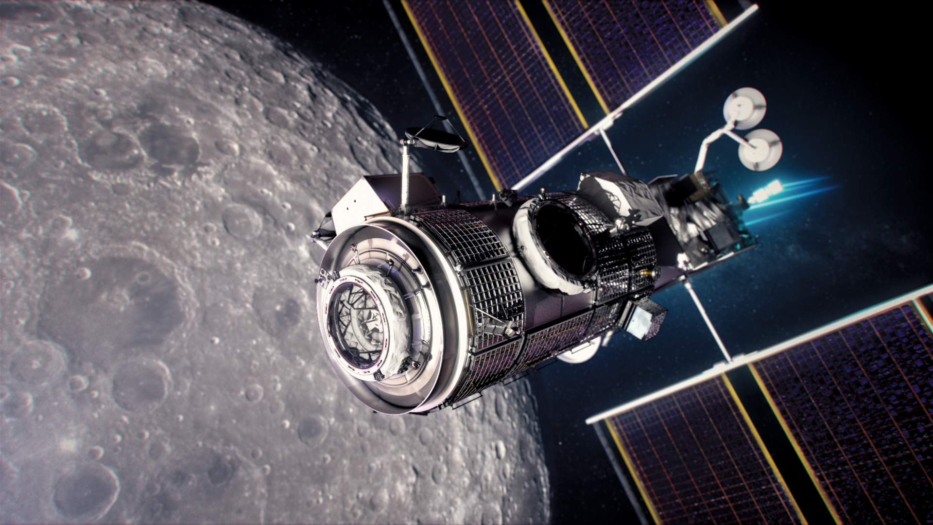
New approaches to streamlining design and constructions standards will benefit projects like the Gateway Power and Propulsion and Habitation and Logistics Outpost.

HALO: Modernized Application of Design & Construction Standards 

The NASA Technical Standards Process Improvement pilot activity initiated by the Habitation and Logistics Outpost (HALO) Project seeks to improve the way that NASA levies and manages technical standards by 1) moving from document-centric to data-centric (databases) management of the requirements; 2) incorporating important attributes into the database so that applicability, tailoring, and information management is streamlined; and 3) providing technical recommendations on acceptable approaches for compliance evidence. The effort is a fleet-leader on how to streamline the standards deployment, assessment, and long-term verification process, while also improving the allocation of resources based on mission risk.   

 NASA Technical Fellows participated in this review and provided important input and support for the assessment of Design and Construction (D&C) standards for the HALO project. The approach “shredded” the requirements documents into a database of individual requirements with fields to populate describing the requirement type and compliance approach. Overall, the pilot activity is an important first step in properly assessing and flowing D&C standards to NASA’s contractors and partners. NESC systems engineering and integration SMEs reviewed the HALO pilot deployment activity for managing and implementing design and construction standards. The SMEs identified advantages and disadvantages of the pilot activity and offered suggestions for improving the standards streamlining effort in the future.

For more information, contact Jennifer Devolites, jennifer.devolites@nasa.gov 

Powered by WPeMatico

Get The Details…
Meagan Chappell

NASA Uses Small Engine to Enhance Sustainable Jet Research

NASA Uses Small Engine to Enhance Sustainable Jet Research

3 min read

Preparations for Next Moonwalk Simulations Underway (and Underwater)

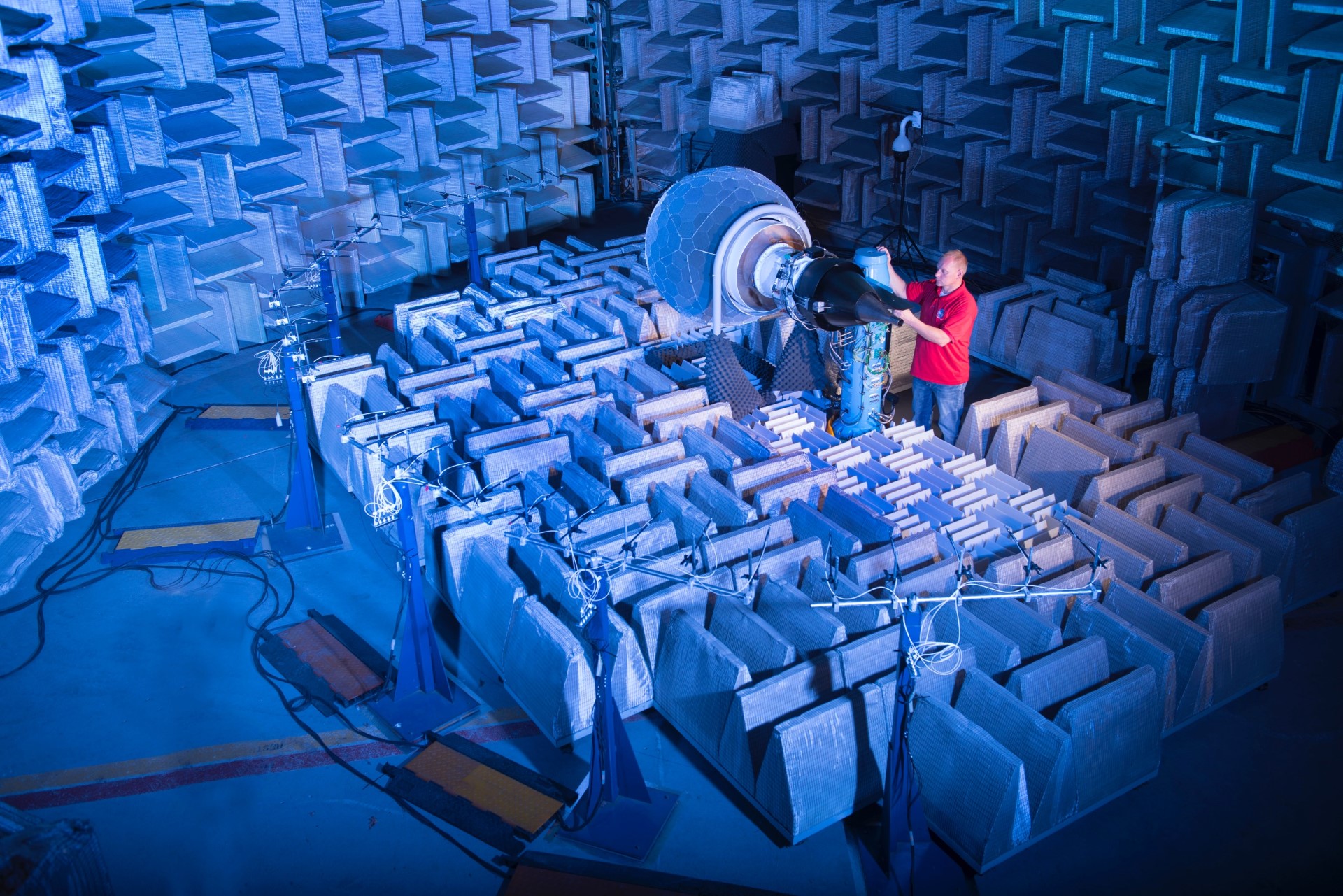
A person stands next to a small jet engine inside a soundproofed room.
The DGEN380 Aero-Propulsion Research Turbofan (DART) is a small-scale jet engine NASA uses to test new aviation technology. DART is seen here inside its host facility, the Aero-Acoustic Propulsion Laboratory at NASA’s Glenn Research Center in Cleveland. This soundproofed chamber ensures researchers can understand the level of noise the engine is producing, as well as keeping the volume low outside.
NASA/Bridget Caswell

Located inside a high-tech NASA laboratory in Cleveland is something you could almost miss at first glance: a small-scale, fully operational jet engine to test new technology that could make aviation more sustainable

The engine’s smaller size and modestly equipped test stand means researchers and engineers can try out newly designed engine components less expensively compared to using a more costly full-scale jet engine test rig. 

Named DGEN380 Aero-Propulsion Research Turbofan, or DART, the engine is tiny enough to fit on a kitchen table, measuring at just 4.3 feet (1.3 meters) long. That’s about half the length of engines used on single-aisle airliners. 

DART – not to be confused with NASA’s asteroid redirect mission of the same name – enables the agency to boost its sustainable aviation technology research because of its accessibility.  

A hidden gem located inside the Aero-Acoustic Propulsion Laboratory at NASA’s Glenn Research Center in Cleveland, the DART engine was made by a French company named Price Induction (now Akira) and was acquired by NASA in 2017. 

“DART’s small size makes it appealing,” said Dan Sutliff, who coordinates research for the engine at NASA Glenn. “It’s a great way to explore new technology that hasn’t yet reached the level of a full-scale operation.” 

Small Steps Towards Big Goals

Several key NASA activities studying jet engines used DART in the past. 

For example, it helped researchers learn more about incorporating materials that can help reduce engine noise. These technologies could be incorporated for use in next-generation airliners to make them quieter. 

Now, NASA researchers plan to use the DART engine to investigate ideas that could help develop new ultra-efficient airliners for use during the 2030s and beyond. If all goes well, the technology could proceed to more exhaustive tests involving larger facilities such as NASA’s wind tunnels. 

“DART is a critical bridge between a design and a wind tunnel test,” Sutliff said. “Technologies that work well here have a greater chance of achieving successful inclusion on future aircraft engines. The test rig helps NASA save resources and contribute to protecting our environment.” 

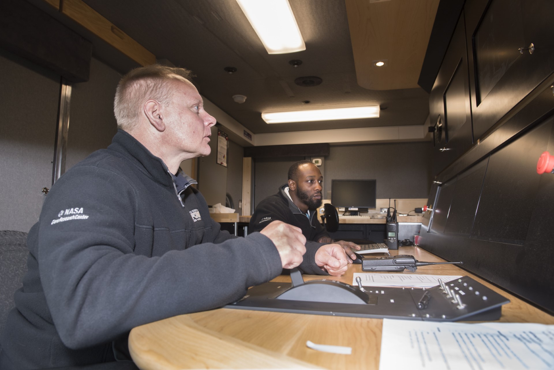
Two people sit at a console desk and supervise data from a jet engine test.
DART tests are run from the Mobile Control Unit – a large van converted into a high-tech control facility with video monitors reporting live data from the engine. In this image, two engineers supervise an engine test, with the nearest researcher operating DART’s thrust lever.
NASA/Bridget Caswell

Among its features, DART has a high bypass ratio, which is a measure of how much air passes through the turbofan and around the main core of the engine as opposed to entering it. Having a high bypass ratio means that DART is more characteristic of larger high-bypass ratio engines on commercial aircraft. 

This design is more fuel efficient than other jet engines and makes DART ideal for testing new propulsion methods alongside NASA’s efforts in developing a small-core, fuel efficient jet engine for commercial airliners in the 2030s. 

The DART engine also can test many other aspects of a jet engine including engine noise, operating controls, coatings used to protect engine parts, sensors and other instrumentation, and much more. 

More information can be found on NASA’s Aero-Acoustic Propulsion Laboratory webpage

About the Author

John Gould

John Gould

Aeronautics Research Mission Directorate

John Gould is a member of NASA Aeronautics’ Strategic Communications team at NASA Headquarters in Washington, DC. He is dedicated to public service and NASA’s leading role in scientific exploration. Prior to working for NASA Aeronautics, he was a spaceflight historian and writer, having a lifelong passion for space and aviation.

Share

Details

Last Updated

Apr 26, 2024

Editor
Jim Banke
Contact
Brian Newbacher

Powered by WPeMatico

Get The Details…
John Gould

Trajectory Reverse Engineering 

Trajectory Reverse Engineering 

A strategy for transferring spacecraft trajectories between flight mechanics tools, called Trajectory Reverse Engineering (TRE), has been developed[1]. This innovative technique has been designed to be generic, enabling its application between any pair of tools, and to be resilient to the differences found in the dynamical and numerical models unique to each tool. The TRE technique was developed as part of the NESC study, Flight Mechanics Analysis Tools Interoperability and Component Sharing, to develop interfaces to support interoperability between several of NASA’s institutional flight mechanics tools.  

The development of space missions involves multiple design tools, requiring the transfer of trajectories between them—a task that demands a large amount of trajectory data such as frames, states, state and time parametrizations, and dynamical and numerical models. This is a tedious and time-consuming task that is not always effective, particularly on complex dynamics where small variations in the models can cause trajectories to diverge in the reconstruction process.   

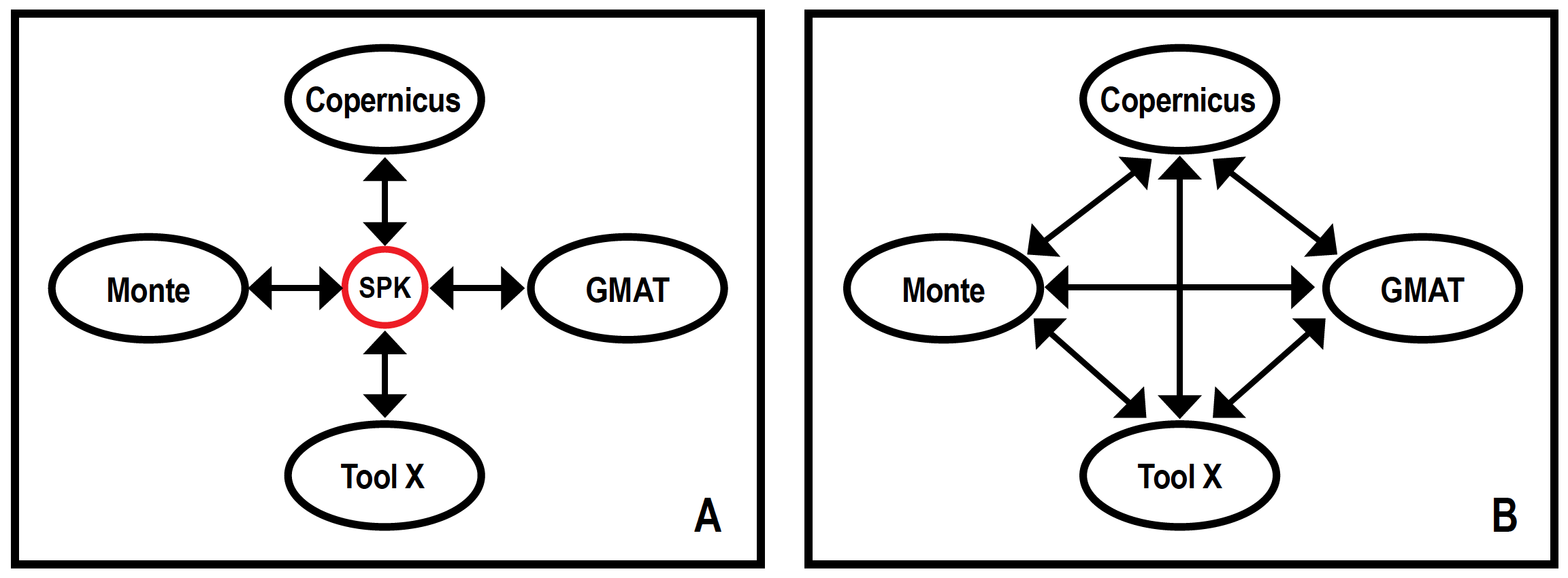
The TRE strategy is a trajectory-sharing process that is agnostic to the models used and performed through a common object: the spacecraft and planet kernels (SPK), developed at JPL Navigation and Ancillary Information Facility. The use of this common object aims to lay the groundwork for a global flight mechanics tool interoperability system (Figure 1). 

Figure 1. A) Interoperability between flight mechanics tools using standardized trajectory structures. B) Traditional specific tool-to-tool interface design.  

An SPK file serves as a container object, representing a trajectory as a 6D invariant structure in phase-space, agnostic to gravitational environments, fidelity models, or numerical representation of the system. A judicious kernel scan is used to recover the trajectory in any new tool, with the minimum (or no) information from the generating source. Impulsive maneuvers can be extracted in the form of velocity discontinuities, finite burns can be detected as variations on the energy of the system, and natural bodies conforming the trajectory universe can be directly read from the kernel.  

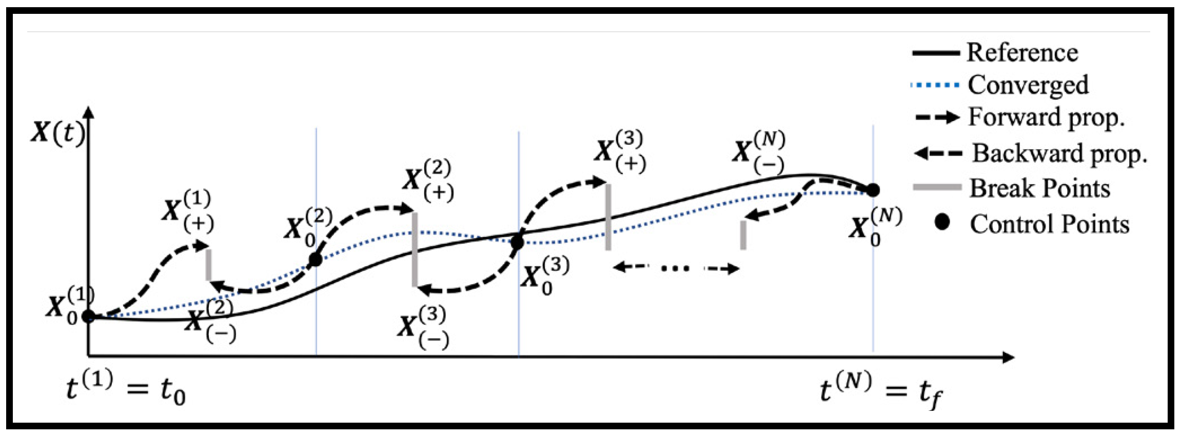
States or control points are found at predetermined time intervals or strategic points along the trajectory (e.g., periapsis, apoapsis, flybys closest approach), which are then used to reconstruct the trajectory timeline. The trajectory can be propagated forward in time using the selected set of control points. Due to the discrepancy between tool models, small or large discontinuities might appear between the integrated legs, which can be smoothed by the implementation of a multiple-shooting algorithm (Figure 2).  

Figure 2. Multiple-shooting algorithm, utilizing strategic control points and a forward-backward propagation scheme. 

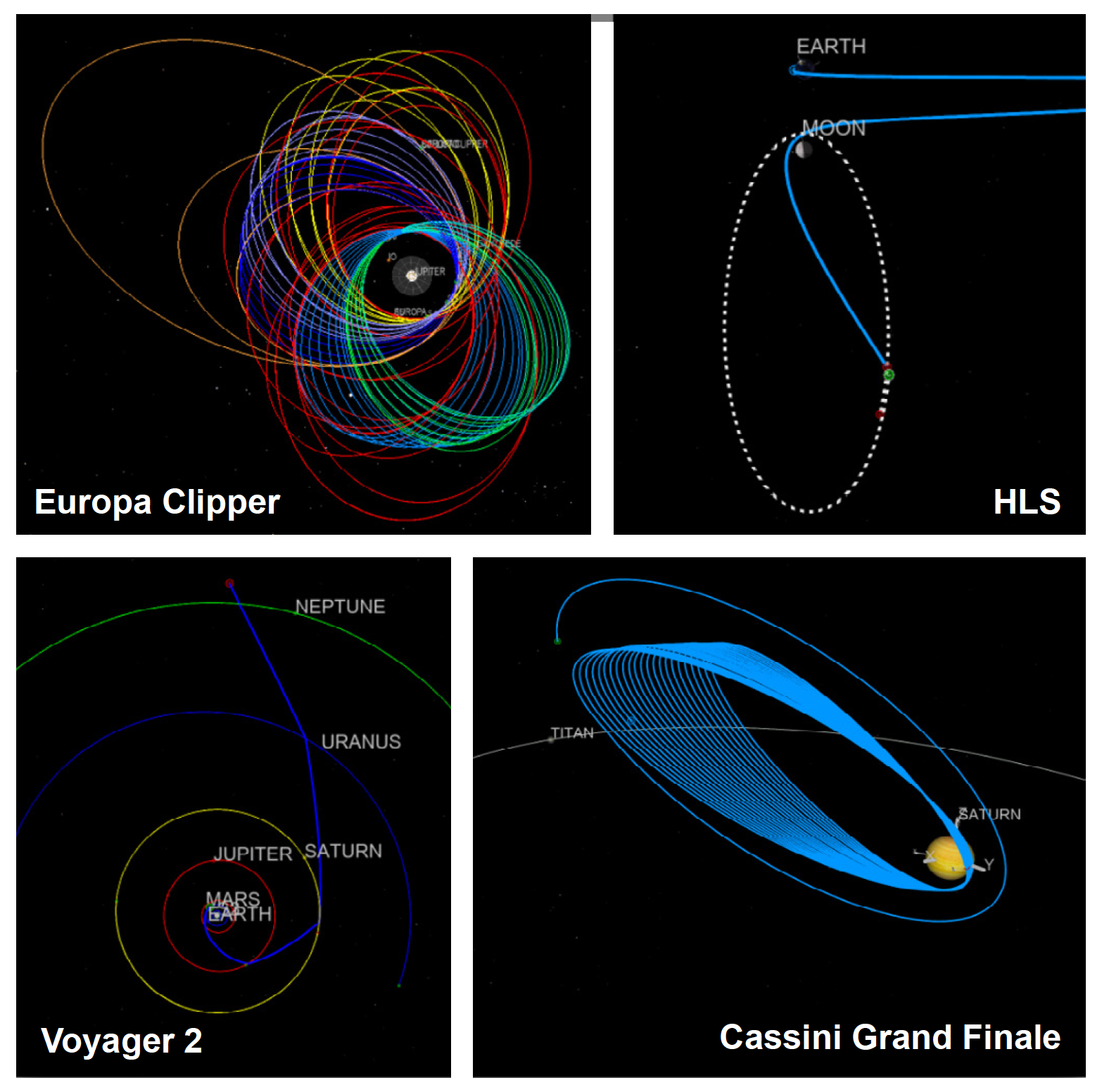
The TRE strategy was successfully implemented for Monte and Copernicus in the form of Python scripts (examples of reconstructed trajectories from SPK for each of these tools are shown in Figure 3). Through an optional user input file, a user can configure their specific problem. User-defined constraints are also possible, but their implementation would depend on the specific tool. The benefits of this effort include cost reduction through the sharing of capabilities, acceleration of the turnaround process involving various analysis tools at different stages of mission development, improved design solutions through multi-tool mission designs, and a reduction in development redundancy. 

Reference: 

  1. Restrepo, R. L., “Trajectory Reverse Engineering: A General Strategy for Transferring Trajectories Between Flight Mechanics Tools” AAS 23-312, January 2023. 
Figure 3. Future and flown missions reconstructions using Copernicus (Europa Clipper, Cassini) and Monte (HLS, Voyager 2) from SPK obtained from the Horizons System database at https://ssd.jpl.nasa.gov/horizons/. 

For information, contact Heather Koehler heather.koehler@nasa.gov and Ricardo L. Restrepo ricardo.l.restrepo@jpl.nasa.gov. 

Powered by WPeMatico

Get The Details…
Meagan Chappell