SPARCS CubeSat ‘First Light’ Images

SPARCS CubeSat ‘First Light’ Images

2 Min Read

SPARCS CubeSat ‘First Light’ Images

This pair of images shows stars observed Feb. 6, 2026, by the SPARCS space telescope simultaneously in the near-ultraviolet, left, and far-ultraviolet, right. The fact that one star is seen in the far-UV while multiple are seen in near-UV offers insights into the temperatures of these stars, with the one visible in both colors being the hottest.
PIA26731
Credits:
NASA/JPL-Caltech/ASU

Description

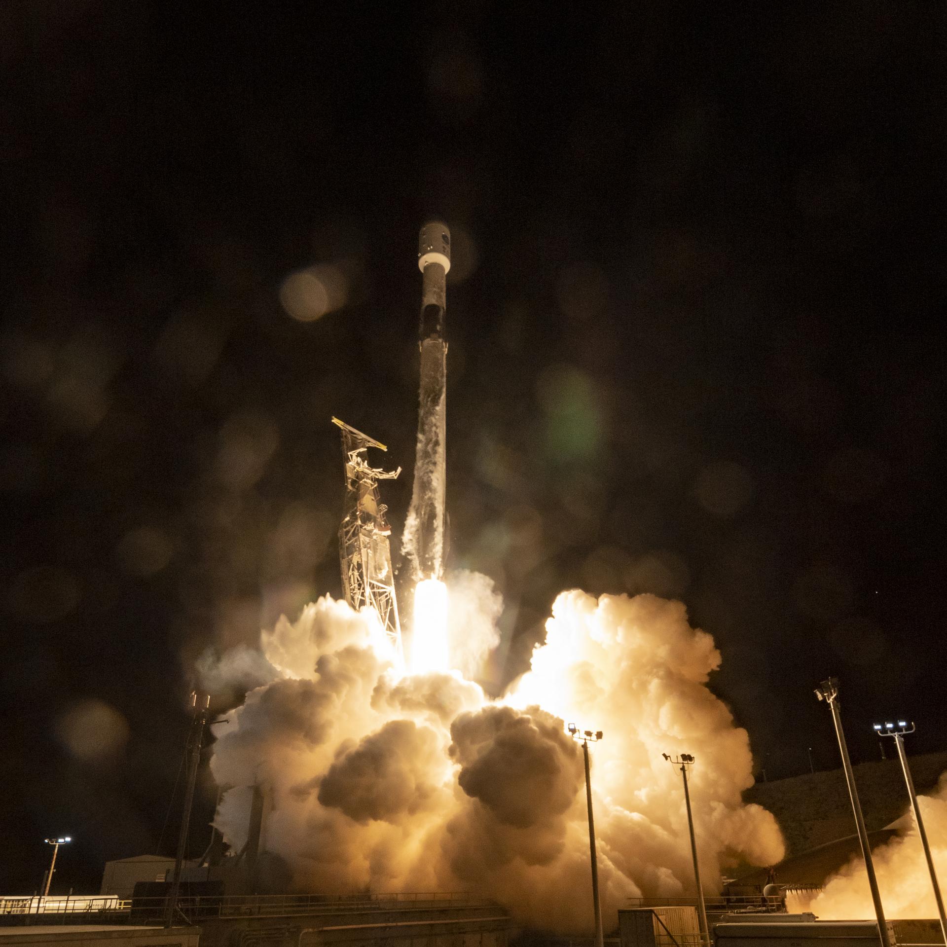
This pair of images shows stars observed by the SPARCS (Star-Planet Activity Research CubeSat) space telescope simultaneously in the near-ultraviolet, left, and far-ultraviolet, right. These observations were recorded on Feb. 6, 2026, three weeks after the cube satellite, or CubeSat, launched aboard a SpaceX Falcon 9 on Jan. 11. The fact that one star is seen in the far-UV while multiple are seen in near-UV offers insights into the temperatures of these stars, with the one visible in both colors being the hottest.

Roughly the size of a large cereal box, SPARCS will monitor flares and sunspot activity on low-mass stars — objects only 30% to 50% the mass of the Sun. These stars are among the most common in the Milky Way and host the majority of the galaxy’s roughly 50 billion habitable-zone terrestrial planets, which are rocky worlds close enough to their stars for temperatures that could allow liquid water and potentially support life.

The SPARCS spacecraft is the first dedicated to continuously and simultaneously monitoring the far-ultraviolet and near-ultraviolet radiation from low-mass stars. Over its one-year mission, SPARCS will target approximately 20 low-mass stars and observe them over durations of five to 45 days. 

Filters for the spacecraft’s camera, SPARCam, were made using a technique that improves sensitivity and performance by enabling them to be directly deposited onto the specially developed UV-sensitive “delta-doped” detectors. The approach of detector-integrated filters eliminated the need for a separate filter element, resulting in a system that is among the most sensitive of its kind ever flown in space.

The filters, detectors, and associated electronics were designed, fabricated, and tested at the Microdevices Laboratory (MDL) at NASA’s Jet Propulsion Laboratory in Southern California. Inventors at MDL harness physics, chemistry, and material science, including quantum, to deliver first-of-their-kind devices and capabilities for our nation.

Funded by NASA and led by Arizona State University in Tempe, SPARCS is managed under the agency’s Astrophysics Research and Analysis program. The agency’s CubeSat Launch Initiative (CSLI) selected SPARCS in 2022 for a ride to orbit. The initiative is a low-cost pathway for conducting scientific investigations and technology demonstrations in space, enabling students, teachers, and faculty to gain hands-on experience with flight hardware design, development, and building.

Blue Canyon Technologies fabricated the spacecraft bus.

Powered by WPeMatico

Get The Details…

To Protect Artemis II Astronauts, NASA Experts Keep Eyes on Sun 

To Protect Artemis II Astronauts, NASA Experts Keep Eyes on Sun 

7 min read

To Protect Artemis II Astronauts, NASA Experts Keep Eyes on Sun 

As four astronauts travel around the Moon on NASA’s Artemis II mission, they will venture beyond Earth’s protective magnetic field. The crew’s spacecraft, Orion, will carry and protect them as they journey into deep space and serves as the main protection against the Sun’s intense power.  During their 10-day flight, NASA and the National Oceanic and Atmospheric Administration (NOAA) will monitor the Sun around the clock and translate space weather conditions into real-time decisions to protect the astronauts. 

Space weather refers to the changing conditions driven by solar wind and eruptions from the Sun. Solar flares are the most powerful eruptions in the solar system, the strongest unleashing more energy than a billion hydrogen bombs. Coronal mass ejections are giant clouds of solar particles hundreds of times the size of Earth that burst from the Sun.  

While both flares and coronal mass ejections can affect technology, the primary concern for astronauts is the solar particle events they can trigger, accelerating some particles to near light speed. If a significant solar particle event occurs near the Artemis II crew, it could raise radiation levels inside the spacecraft. Too high a total lifetime exposure can contribute to increased risks of developing cancer or health disorders that could impair cognition and performance. During the Artemis II mission, NASA will minimize that risk.

For the first time in half a century, four astronauts are leaving Earth’s protective magnetic field to enter a realm where massive solar eruptions can unleash more energy than a billion hydrogen bombs. The Artemis II crew will fly through a dangerous environment, but they’re not going it alone. On the voyage, the astronauts and their Orion capsule are outfitted with radiation trackers as ground teams monitor solar eruptions 24/7. Here’s how NASA and the National Oceanic and Atmospheric Administration (NOAA) are protecting explorers from the most powerful eruptions in the solar system.
NASA/Joy Ng

Tracking solar eruptions 

“Our focus will be real-time space weather analysis, prioritizing solar energetic particles and events that could produce them,” said Mary Aronne, operations lead for the space weather analysis office at NASA’s Goddard Space Flight Center in Greenbelt, Maryland. “We’re looking for the trigger, which would typically be a flare or a coronal mass ejection.” 

This animation shows a solar eruption that produces a solar flare, a coronal mass ejection, and a flurry of energetic particles. The particles follow the spiral shape of the solar wind’s magnetic fields into interplanetary space.
NASA’s Goddard Space Flight Center Conceptual Image Lab

The Goddard team will track any solar eruptions that occur, measuring how big they are, how fast they’re moving, and how likely they are to generate energetic particles that will cross Orion’s path. To this end, they’ll use real-time data from Sun-watching spacecraft strategically placed across the solar system, such as NASA’s recently launched Interstellar Mapping and Acceleration Probe, NASA’s Solar Dynamics Observatory, the ESA (European Space Agency)/NASA Solar and Heliospheric Observatory, NOAA’s Geostationary Operational Environmental Satellites-19 satellite, and many others. 

Other NASA spacecraft also will help monitor the Sun. Due to Mars’ current position, NASA’s Perseverance Mars rover can look at the far side of the Sun, where Earth has no view. The rover’s Mastcam-Z cameras can give NASA’s space weather teams a view of the largest sunspots up to two weeks earlier so the team can monitor and prepare for possible solar flares.  

NASA’s Perseverance Rover captured these images of sunspots crossing the Sun from its vantage point on the Martian surface between February 24 – 27, 2026. Mars is currently on the opposite side of the Sun, giving the rover a view of sunspots not visible from Earth. Perseverance will monitor sunspots leading up to and during the Artemis II launch window, giving the Moon to Mars Space Weather Analysis Office (M2M SWAO) and Space Radiation Analysis Group (SRAG) teams advance notice of regions that could produce solar eruptions before they rotate onto the Earth-facing side of the Sun.
NASA/JPL-Caltech/ASU/MSSS/SSI

Monitoring crew exposure 

Energetic solar particles don’t stream straight out from the Sun. They spiral along the Sun’s magnetic field lines, tracing loops tens of thousands of miles across and scattering due to particle collisions along the way. The chaotic swarm is so large that, from inside it, particles seem to be coming from every direction.  

“It’s more like you’re sitting in a bathtub and it’s gradually filling with water,” said Stuart George, a space radiation analyst at NASA Johnson. 

That gradual rise in radiation gives analysts time to evaluate the situation. Inside Orion, six radiation sensors, part of the Hybrid Electronic Radiation Assessor system designed and built by NASA, measure dose rates in different parts of the cabin. Artemis II astronauts also wear personal radiation trackers called crew active dosimeters. If radiation levels increase, Orion’s onboard systems display warnings accompanied by an audible alarm. 

Exploded diagram of NASA's Orion spacecraft showing labeled parts: spacecraft adapter, service module, crew module, and launch abort system, with various components highlighted against a gray background.
Artist’s concept of the components of the Orion spacecraft.
NASA

NASA has dosage level thresholds they’ll look for inside Orion. The first threshold signals a caution, prompting closer monitoring and coordination with medical and flight operations teams. A higher threshold triggers a recommendation for the crew to take shelter. 

Radiation shielding in space is all about mass. Charged particles are slowed and absorbed as they pass through matter. Astronauts are trained to reconfigure their cabin during a solar particle event, removing stowed equipment from storage bays and securing it along areas of the cabin to add mass between themselves and incoming particles. Since Artemis II is the first crewed Artemis mission, testing this procedure in the Orion spacecraft is a major objective of the mission. 

“Once crews add mass to the places that tend to be hotter in terms of radiation exposure, they can then continue to go about their duties,” George said. 

Artist’s concept of the Trajectory for Artemis II, NASA’s first flight with crew aboard SLS and Orion to pave the way for long-term return to the Moon and missions to Mars.
NASA

The complexity of solar particle events is one reason NASA places spacecraft across the solar system. During a solar storm in January, NASA analysts tracked a coronal mass ejection on its way to Earth. When it arrived, satellites detected two distinct spikes in energetic particles where there would normally be one. Measurements from NASA’s BioSentinel CubeSat, deployed during the Artemis I mission, revealed what happened. The spacecraft, about 55 million miles away from Earth, detected a distinct eruption that later merged with the coronal mass ejection headed to Earth. Ultimately, two separate eruptions occurred.

The crew also must account for exposure to Earth’s radiation belts and galactic cosmic rays. The Van Allen Radiation Belts are two rings of high energy particles that surround our planet. Any mission headed to the Moon or farther must pass through them. Galactic cosmic rays are very high-energy particles from sources beyond our solar system. Together, the radiation exposure from these sources is expected to be comparable to a 1-month stay on the International Space Station, or about 5% of an astronaut’s career limit. Any exposure from solar radiation events would add to this baseline. 

The Moon to Mars Space Weather Analysis Office, based at NASA Goddard, continuously assesses solar activity and any eruptions that occur. The team shares its analysis with the Space Radiation Analysis Group, based at NASA’s Johnson Space Center in Houston. Together, their forecasts and those from NOAA’s Space Weather Prediction Center, plus real-time measurements from inside the Orion spacecraft will inform recommendations for the flight control team.  

By Miles Hatfield
NASA’s Goddard Space Flight Center, Greenbelt, Md.

Keep Exploring

Discover More Topics From NASA

Powered by WPeMatico

Get The Details…

Celebrating 100 Years Since Goddard’s Breakthrough Moment in Modern Rocketry

Celebrating 100 Years Since Goddard’s Breakthrough Moment in Modern Rocketry

On a snowy March 16, 1926, Dr. Robert H. Goddard rests his hand on the testing frame supporting his liquid fuel rocket at Ward Farm in Auburn, Massachusetts. A wooden door is propped up at an angle next to the frame where Goddard’s assistant, Henry Sachs, later sheltered after lighting the rocket.
Dr. Robert H. Goddard and a liquid oxygen-gasoline rocket in the frame from which it was fired on March 16, 1926, at Auburn, Mass.
Esther Goddard, from the Clark University archive

From the voyages of spacecraft to the Moon and beyond, to the launches of satellites that help us navigate, communicate, and understand our planet and the universe, the use of liquid-fueled rockets has been key to humanity’s use and exploration of space. Today marks 100 years since the first successful test of this technology.

On March 16, 1926, physicist and inventor Dr. Robert H. Goddard achieved a small but significant success when he launched a liquid-fueled rocket for the first time. His rocket, fueled by liquid oxygen and gasoline, was tested at his Aunt Effie’s farm in Auburn, Massachusetts.

While unimpressive by most measures—the rocket flew for just 2.5 seconds, reaching 41 feet (12.5 meters) in altitude and landing in a cabbage patch 184 feet (56 meters) away—it was a breakthrough that heralded the exploration of space.

Over his lifetime, Goddard improved on his design and went on to create other technologies for space travel, including systems to steer rockets, pumps for rocket fuels, and engines that could pivot for better control. His pioneering work laid an important foundation for our achievements in space today.

Photo Credit: Esther Goddard, from the Clark University archive.

Powered by WPeMatico
Get The Details…
Michele Ostovar

A Combination of Techniques Leads to Improved Friction Stir Welding 

A Combination of Techniques Leads to Improved Friction Stir Welding 

Download PDF: A Combination of Techniques Leads to Improved Friction Stir Welding

The NESC developed several innovative tools and techniques during an assessment to find the root cause of poor tensile strength and low topography anomalies (LTA) in welds formed using a solid-state welding process called self-reacting friction stir welding (SRFSW).   

Using a combination of machine learning, statistical modeling, and physics-based simulations, the assessment team helped improve the weld process and solve both issues, lifting constraints that had been placed on flight hardware.  

Developing Techniques for LTA Detection 

Determining the root cause of poor tensile strength welds and LTA observed on the weld fracture surfaces involved several techniques: 

  • Deep Learning for LTA Detection: The NESC team developed a machine-learning model to detect and segment LTA in weld images. The model was trained on images annotated by metallurgy experts, with a majority-vote consensus to resolve disagreements. The team then developed an accompanying standard operating procedure for image capture to improve robustness and reduce bias. This model was built on previous NASA work to develop specialty microscopy analysis foundation models by pretraining on 100,000+ microscopy images. This step was crucial to linking process parameters with LTA occurrence in an objective, nonbiased way. 
The team eliminated issues with manual identification of LTA by training a neural network to detect LTA from images of fracture surfaces, pretraining an encoder on a large NASA dataset of microscopy images called MicroNet.
  • Integrated Data-Ingestion Framework: SRFSW is a complex process with many interacting variables. The weld process produces a large amount of data with diverse data types that include dozens of tabular process parameters, dozens of sequential data streams from the production tool, fracture and weld cross-section images, and mechanical-test lab data. A Python-based framework was developed to automatically ingest and validate these diverse data and compile them into a single master spreadsheet and a database. This tool reduced manual effort, minimized transcription errors, and improved data quality for downstream analysis. The team delivered the tool to stakeholders for their ongoing use. 

Diagram labeled ‘Data Ingestion Framework’ showing a three‑step flow. Left circle lists data sources including weld stream data, test data, microstructural measurements, and defect analyses. An arrow leads to a center circle labeled ‘Data Automatically Ingested into Python,’ which then flows to a right circle labeled ‘Master Spreadsheet & Materials Database.’ A caption explains that the pipeline integrates processing parameters, microstructure, and mechanical performance for SRFSW.

  • Data Analysis Web Application: A new web-based visualization and analysis tool allowed engineers and subject matter experts to quickly explore the integrated dataset for faster hypothesis testing and more intuitive insight generation throughout the investigation
  • Space-Filling Design of Experiments: Because SRFSW involves complex, nonlinear relationships between process parameters, the team found traditional factorial designs were insufficient and implemented a space-filling design of experiments (DOE) to efficiently explore the full parameter space. These data-trained machine-learning models capture the underlying weld behavior. The team also developed a software tool for generating such designs and shared it with stakeholders.

Side‑by‑side 3D scatter plots comparing initial data with a space‑filling design of experiments. The left plot shows red points clustered tightly in a narrow band, while the right plot shows red and blue points spread evenly throughout the entire 3D space. Caption states that space‑filling DOE provides better coverage for machine learning

  • Physics-Based SRFSW Simulation: Creating a computational model of the SRFSW process simulated weld conditions, microstructure evolution, and resulting properties, offering insight into aspects of the weld process that are inaccessible to physical sensors. This enhanced understanding and guided improvements. 

Determining LTA Root Cause 

Using these tools and analyses, the team identified two root causes for the LTA and poor tensile strength: 

  1. Overly aggressive post-weld surface preparation in production reduced weld strength. 
  1. Weld power input outside the optimal range led to inconsistent welds and increased risk of LTA. 

The process models helped define a target weld power input window and recommended how to adjust primary control parameters to reliably achieve that target. Follow-up production tests confirmed that these adjustments could be implemented with high precision, eliminating both low-strength welds and LTA.  

Friction Stir Welding 

In SRFSW, a rotating pin is plunged into the seam between two metal plates, generating heat through friction that fuses the sheets together without melting the material. This technique produces stronger joints than traditional welding and enables the use of high-performance but traditionally non-weldable alloys like Aluminum 2219. 

The SRFSW technique uses no blowtorches or solder because friction stirs the materials together at a molecular level.

 Rotating tool applying pinch force to form or fasten sheet material, converting rotation into controlled lateral travel.

Interior of a tall industrial assembly building showing a large yellow‑green cylindrical aerospace structure held within a multi‑story blue steel support and processing tower. Surrounding the assembly are white and yellow access platforms, scaffolding, and bright overhead lighting. A few workers stand near the base, emphasizing the enormous scale of the structure

NASA’s Friction Stir Welding lab resides inside NASA’s Michoud Vertical Assembly Center in New Orleans and is being used to join major components of the SLS rocket. 

For information, contact Donald S. Parker.  donald.s.parker@nasa.gov 

References: NASA/TM-20240016466 and NASA/TM-20230010624 

Powered by WPeMatico
Get The Details…
Meagan Chappell

NESC Develops Method for Estimating Risk When Reducing NDE 

NESC Develops Method for Estimating Risk When Reducing NDE 

Download PDF: NESC Develops Method for Estimating Risk When Reducing NDE 

Performing nondestructive evaluation (NDE) can have both cost and schedule impacts, leading some to question whether descoping (i.e., reducing or eliminating) NDE inspections on certain spaceflight hardware could be possible. However, this approach would be counter to NASA’s Technical Standard NASA-STD-5019A, which outlines the spaceflight system requirements for establishing a fracture control plan—one that relies on design, analysis, testing, NDE, and tracking of fracture-critical parts to verify damage tolerance and mitigate catastrophic failure. 

Under the 5019A framework, damage smaller than the NDE detection capability is assumed to exist, but through analysis or test, the part being evaluated must be shown to survive the required service life. In practice, NDE’s role is to screen out flaws that otherwise may result in failure. However, in some cases, descoping NDE from the damage tolerance verification process could be useful and still provide the required level of safety.   

The NESC conducted an assessment to help answer the question of whether rationale could be found for achieving an equivalent risk posture without using the traditional 5019A approach to damage tolerance. The objective was to develop a probabilistic analysis method that would allow NASA programs and projects to estimate risk associated with descoping the NDE requirements of single-wrought materials. This effort included using historical data to demonstrate the method, performing sensitivity studies, and identifying the minimum supporting data that would be required for approving a descoping request. 

Descoping NDE from Damage Tolerance 

Damage tolerance is typically treated as deterministic: an NDE detection threshold is established as a fixed flaw size with an associated binary outcome (flaw exists/does not exist), and failure is based on a conservative analysis or test with a binary result (pass/fail). However, damage tolerance is rooted in the following probabilities:  

•  P(A): Probability that a flaw of a given size exists, 

•  P(D0A): Probability that this flaw will be missed by NDE, and  

•  P(FD0,A): Probability that a flaw results in failure given that it exists and was missed by NDE.  

These are combined into the joint failure probability: P(F,D0,A) = P(F│D0,A)P(D0│A)P(A) 

Damage tolerance is based on the idea that analysis and testing suggests a near-zero probability of failure below a critical initial flaw size (aCIFSshown by the green (lower) arrow in Figure 1, and NDE results in a near-zero probability of missing a flaw above some detectability threshold (aNDE) shown by the yellow (upper) arrow in Figure 1. If these two areas overlap, then the part is damage tolerant, with a near-zero failure probability regardless of underlying probability of flaw existence, i.e., conservatively assuming that P(a>aCIFS)=1 for any flaw size does not impact the conclusion. However, if NDE is descoped, it removes the right arrow from Figure 1, and risk will increase to a value proportional to the probability P(a>aCIFS)

A probabilistic interpretation of damage tolerance

Estimating P(a>aCIFS) may be intractable without expensive, high-resolution methods to characterize the frequency of flaw occurrence at a particular size for a given part. Alternatively, it may be possible to estimate P(a> aNDE), the probability of a detectable flaw existing. Assuming that a part of interest is shown to be damage tolerant prior to any NDE descope (i.e., satisfying NASA-STD-5019A), it can be assumed that (1) historical inspection data are available, and (2) aNDE > aCIFS, due to the required overlap in Figure 1. As such, it was proposed that the frequency of historical finds could be used to estimate a 95% upper confidence bound on P(a> aNDE) and thus an estimate of the risk associated with descoping. 

To demonstrate the risk-evaluation framework, the NESC gained access to a historical NDE database comprising 33,630 bolt-hole inspections over a 3-year period. In total, six crack-like features were found by NDE. Accounting for uncertainty due to sample size yielded a 95% confidence upper bound of P(a> aNDE= 0.04% for each hole. In the proposed method, it is conservatively assumed that if a flaw exceeding the CIFS exists, then it will lead to structural failure. While conservative, this assumption was necessary based on the limitations of the database in that it lacked detected flaw sizing. Based on this assumption, P(a> aNDE) = 0.0004 yields a structural reliability of approximately 0.9996 (expressed as 3.4 “nines”).  

The results are illustrated graphically in Figure 2. In this case study, increasing the number of inspections in the dataset to 100,000 (i.e., multiplying by a factor of 3) marginally increases the number of nines to 3.5. At the observed NDE rejection rate, 4 nines of reliability are not achievable even with infinite samples and zero uncertainty. It is expected that the rejection rates and sample sizes in this case study are on the order of magnitude of what would be observed and available in practice. Since 2 nines or less would equate to a significant increase relative to the baseline risk for NASA Human Spaceflight Programs, a minimum sample size of 5,000 inspections is needed at an NDE rejection rate of 0.04%. 

95% confidence upper bound on risk as a function of total inspections and proportion of rejections

Flowchart of the proposed approach for assessing risk associated with NDE descope

There are necessary assumptions underpinning this methodology. First, time-invariant process control is required to ensure that estimated probabilities from historical inspections are predictive of future probabilities after descope. Ensuring consistency during the data collection period is a first step in verifying existing controls, and continued monitoring is necessary to verify that the process remains time-invariant. Second, while aggregating data across multiple parts can increase the inspection sample size and decrease uncertainty in estimated rejection rates, it requires aggregation rationale via qualitative and quantitative assessments of similitude. The methodology developed by the NESC is intended to be a component of a comprehensive fracture control evaluation by the NASA Fracture Control Board and the responsible Technical Authority.  

For information, contact Patrick E. Leser.  patrick.e.leser@nasa.gov 

Reference: NASA/TM-20250004074 

Powered by WPeMatico
Get The Details…
Meagan Chappell