Straight Shot: Hubble Investigates Galaxy with Nine Rings
5 Min Read
Straight Shot: Hubble Investigates Galaxy with Nine Rings
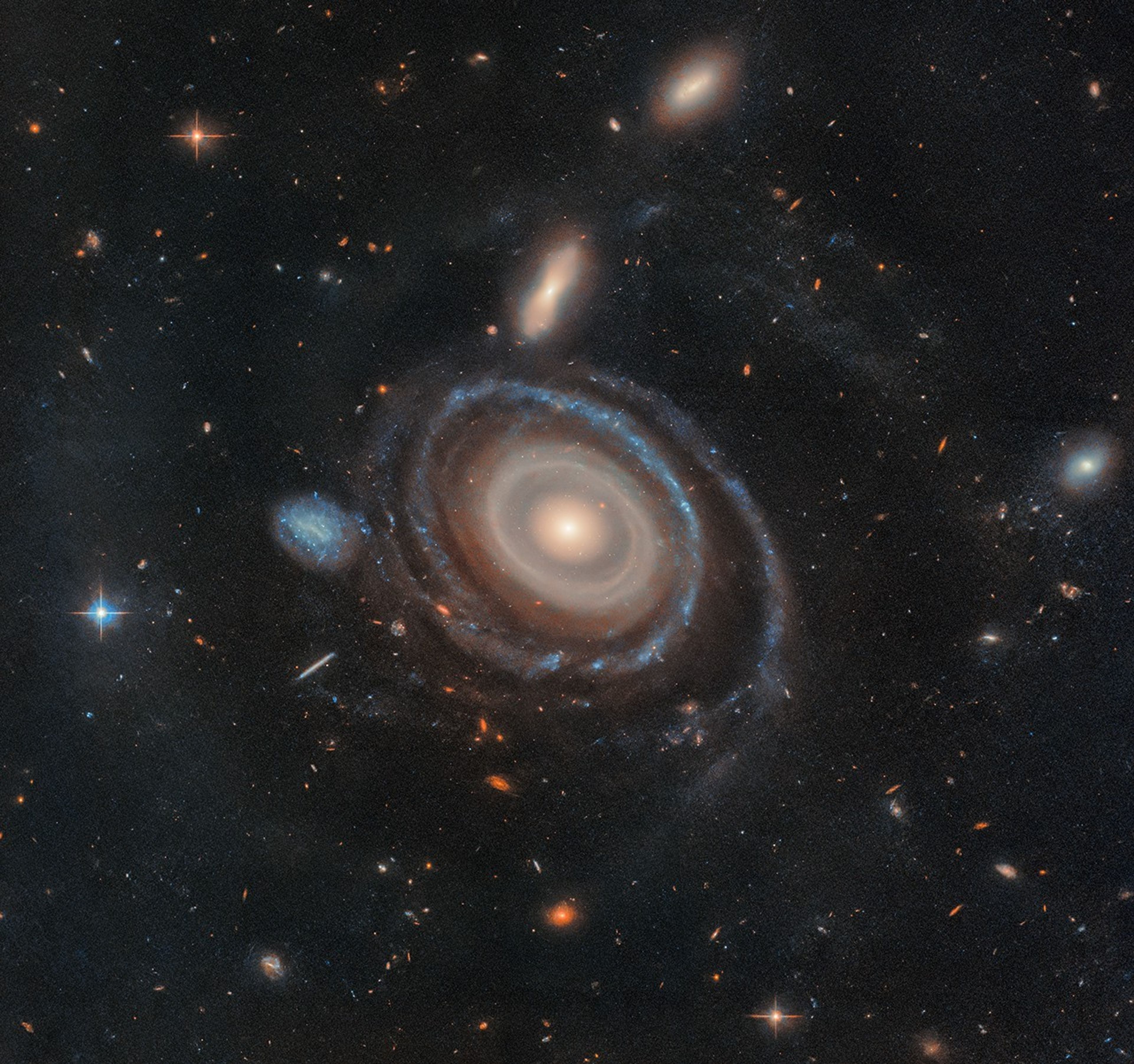
LEDA 1313424, aptly nicknamed the Bullseye, is two and a half times the size of our Milky Way and has nine rings — six more than any other known galaxy.
Credits: NASA, ESA, Imad Pasha (Yale), Pieter van Dokkum (Yale)
NASA’s Hubble Space Telescope has captured a cosmic bullseye! The gargantuan galaxy LEDA 1313424 is rippling with nine star-filled rings after an “arrow” — a far smaller blue dwarf galaxy — shot through its heart. Astronomers using Hubble identified eight visible rings, more than previously detected by any telescope in any galaxy, and confirmed a ninth using data from the W. M. Keck Observatory in Hawaii. Previous observations of other galaxies show a maximum of two or three rings.
“This was a serendipitous discovery,” said Imad Pasha, the lead researcher and a doctoral student at Yale University in New Haven, Connecticut. “I was looking at a ground-based imaging survey and when I saw a galaxy with several clear rings, I was immediately drawn to it. I had to stop to investigate it.” The team later nicknamed the galaxy the “Bullseye.”
LEDA 1313424, aptly nicknamed the Bullseye, is two and a half times the size of our Milky Way and has nine rings — six more than any other known galaxy. High-resolution imagery from NASA’s Hubble Space Telescope confirmed eight rings, and data from the W. M. Keck Observatory in Hawaii confirmed a ninth. Hubble and Keck also confirmed which galaxy dove through the Bullseye, creating these rings: the blue dwarf galaxy that sits to its immediate center-left.
NASA, ESA, Imad Pasha (Yale), Pieter van Dokkum (Yale)
Hubble and Keck’s follow-up observations also helped the researchers prove which galaxy plunged through the center of the Bullseye — a blue dwarf galaxy to its center-left. This relatively tiny interloper traveled like a dart through the core of the Bullseye about 50 million years ago, leaving rings in its wake like ripples in a pond. A thin trail of gas now links the pair, though they are currently separated by 130,000 light-years.
“We’re catching the Bullseye at a very special moment in time,” said Pieter G. van Dokkum, a co-author of the new study and a professor at Yale. “There’s a very narrow window after the impact when a galaxy like this would have so many rings.”
Galaxies collide or barely miss one another quite frequently on cosmic timescales, but it is extremely rare for one galaxy to dive through the center of another. The blue dwarf galaxy’s straight trajectory through the Bullseye later caused material to move both inward and outward in waves, setting off new regions of star formation.
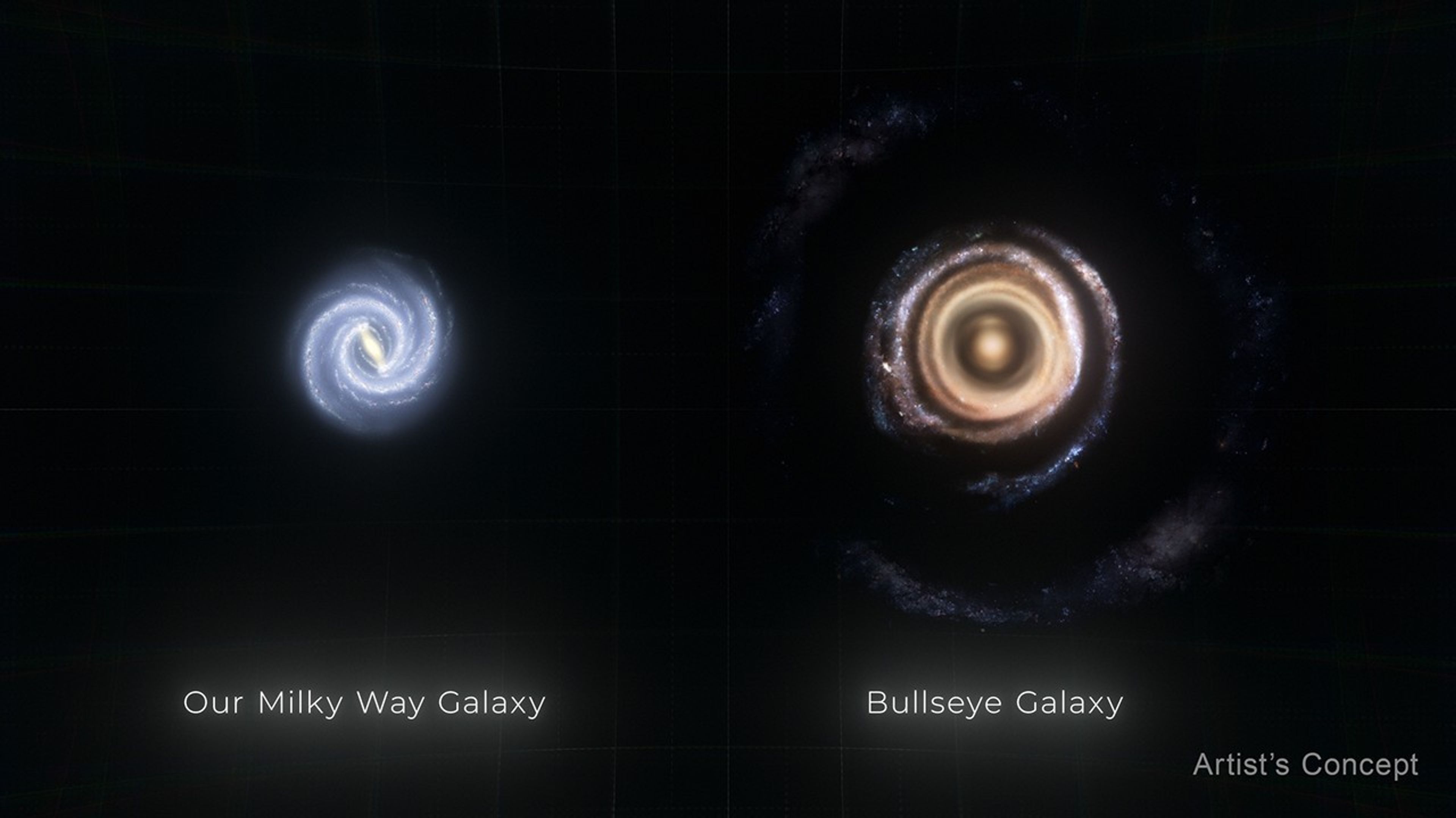
How big is the Bullseye? Our Milky Way galaxy is about 100,000 light-years in diameter, and the Bullseye is almost two-and-a-half times larger, at 250,000 light-years across.
This illustration compares the size of our own Milky Way galaxy to gargantuan galaxy LEDA 1313424, nicknamed the Bullseye. The Milky Way is about 100,000 light-years in diameter, and the Bullseye is almost two-and-a-half times larger, at 250,000 light-years across.
The researchers used Hubble’s crisp vision to carefully to pinpoint the location of most of its rings, since many are piled up at the center. “This would have been impossible without Hubble,” Pasha said.
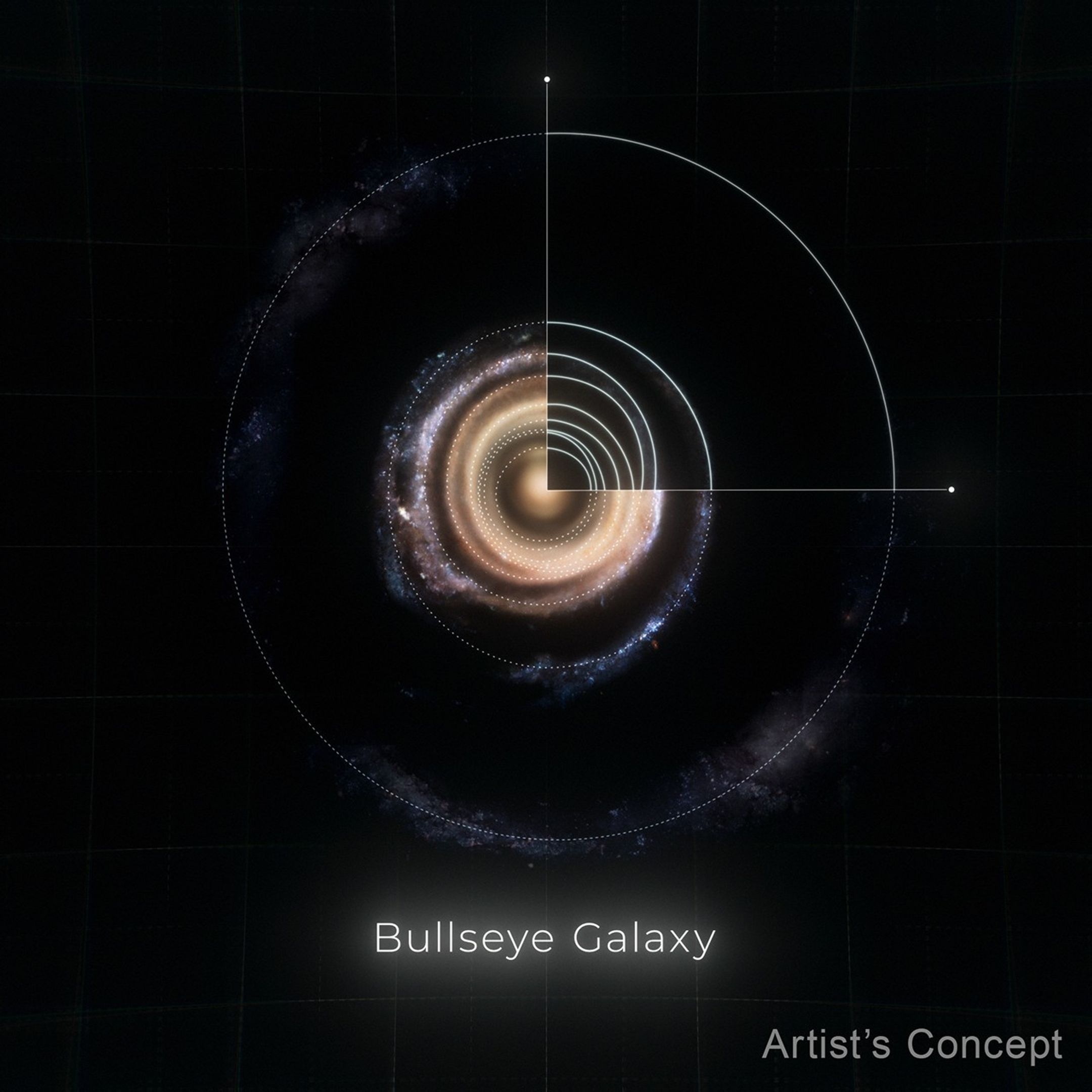
They used Keck to confirm one more ring. The team suspects a 10th ring also existed, but has faded and is no longer detectable. They estimate it might lie three times farther out than the widest ring in Hubble’s image.
A One-to-One Match with Predictions
Pasha also found a stunning connection between the Bullseye and a long-established theory: The galaxy’s rings appear to have moved outward almost exactly as predicted by models.
“That theory was developed for the day that someone saw so many rings,” van Dokkum said. “It is immensely gratifying to confirm this long-standing prediction with the Bullseye galaxy.”
If viewed from above, it would be more obvious that the galaxy’s rings aren’t evenly spaced like those on a dart board. Hubble’s image shows the galaxy from a slight angle. “If we were to look down at the galaxy directly, the rings would look circular, with rings bunched up at the center and gradually becoming more spaced out the farther out they are,” Pasha explained.
To visualize how these rings may have formed, think about dropping a pebble into a pond. The first ring ripples out, becoming the widest over time, while others continue to form after it.
The researchers suspect that the first two rings in the Bullseye formed quickly and spread out in wider circles. The formation of additional rings may have been slightly staggered, since the blue dwarf galaxy’s flythrough affected the first rings more significantly.
This illustration shows the massive galaxy nicknamed the Bullseye face-on. Dotted circles indicate where each of its rings are, which formed like ripples in a pond after a blue dwarf galaxy (not shown) shot through its core about 50 million years ago. NASA’s Hubble Space Telescope helped researchers carefully pinpoint the location of most of its rings, many of which are piled up at the center. Data from the W. M. Keck Observatory in Hawaii helped the team confirm another ring.
Individual stars’ orbits were largely undisturbed, though groups of stars did “pile up” to form distinguishable rings over millions of years. The gas, however, was carried outward, and mixed with dust to form new stars, further brightening the Bullseye’s rings.
There’s a lot more research to be done to figure out which stars existed before and after the blue dwarf’s “fly through.” Astronomers will now also be able to improve models showing how the galaxy may continue to evolve over billions of years, including the disappearance of additional rings.
Although this discovery was a chance finding, astronomers can look forward to finding more galaxies like this one soon. “Once NASA’s Nancy Grace Roman Space Telescope begins science operations, interesting objects will pop out much more easily,” van Dokkum explained. “We will learn how rare these spectacular events really are.”
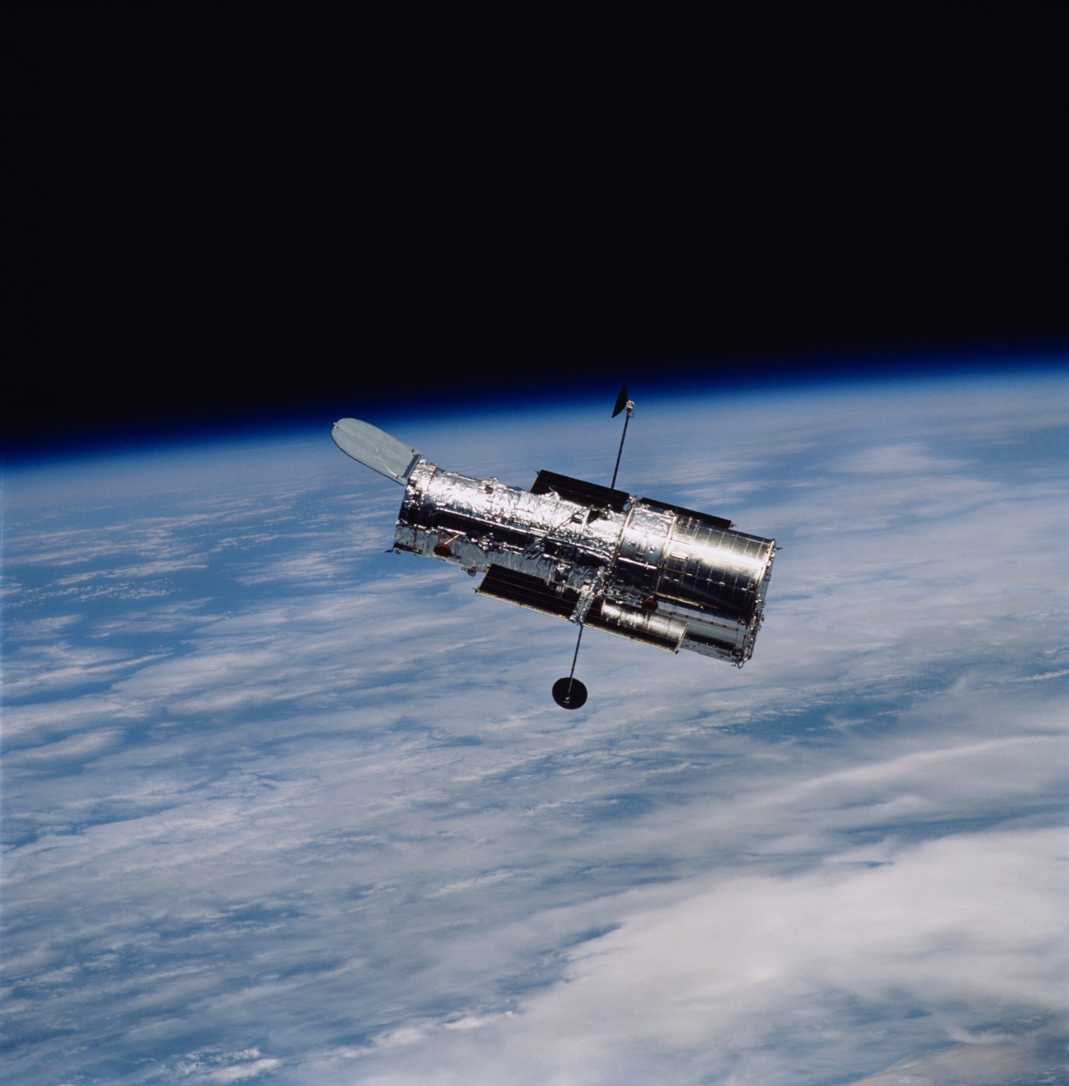
The Hubble Space Telescope has been operating for over three decades and continues to make ground-breaking discoveries that shape our fundamental understanding of the universe. Hubble is a project of international cooperation between NASA and ESA (European Space Agency). NASA’s Goddard Space Flight Center in Greenbelt, Maryland, manages the telescope and mission operations. Lockheed Martin Space, based in Denver, also supports mission operations at Goddard. The Space Telescope Science Institute in Baltimore, which is operated by the Association of Universities for Research in Astronomy, conducts Hubble science operations for NASA.
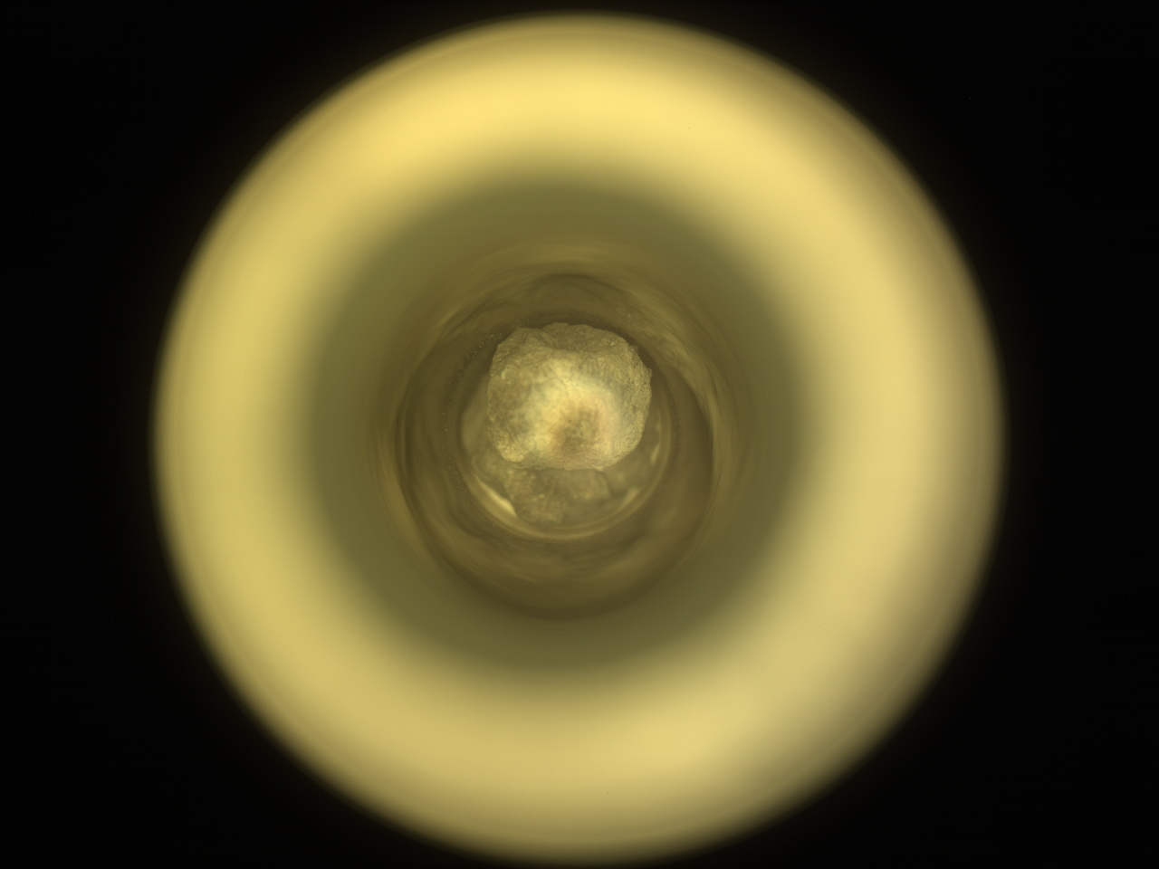
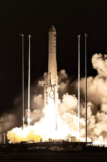
NASA’s Mars Perseverance rover acquired this image of its 26th collected rock sample, “Silver Mountain,” using its onboard Sample Caching System Camera (CacheCam), located inside the rover underbelly. It looks down into the top of a sample tube to take close-up pictures of the sampled material and the tube as it’s prepared for sealing and storage. This image was acquired on Jan. 28, 2025 — sol 1401, or Martian day 1,401 of the Mars 2020 mission — at the local mean solar time of 18:49:01.
NASA/JPL-Caltech
The Mars 2020 Perseverance rover continues to live up to its name, pushing forward in search of ancient Martian secrets. Following a brief period of system verification and remote testing, our operations team is back at full strength, and Perseverance has been hard at work uncovering new geological insights.
We began our latest campaign at “Mill Brook,” a site surrounded by dusty, fine-grained paver stones. Here, we conducted an abrasion experiment at “Steve’s Trail,” allowing our remote sensing instruments to capture a before-and-after analysis of the rock surface. SuperCam (SCAM) used its LIBS and VISIR systems to investigate “Bad Weather Pond,” while Mastcam-Z (ZCAM) imaged the entire workspace. These observations provide invaluable data on the composition, texture, and potential alteration of these rocks.
After wrapping up at Mill Brook — including a ZCAM multispectral scan of “Berry Hill” — Perseverance took a 140-meter drive (about 459 feet) to “Blue Hill” at “Shallow Bay,” a site of immense scientific interest. The rocks here are rich in low-calcium pyroxene (LCP), making them one of the most intriguing sample targets of the mission so far.
The significance of Blue Hill extends beyond just this one location. The pyroxene-rich nature of the site suggests a potential link to a much larger rock unit visible in orbital HiRISE images. Given that this may be the only exposure of these materials within our planned traverse, our science team prioritized sampling this Noachian-aged outcrop, a rare window into Mars’ deep past.
And now, we are thrilled to announce:
Perseverance has successfully cored and sealed a 2.9-centimeter (1.1-inch) rock sample from Blue Hill, officially named “Silver Mountain.” This marks our first Noachian-aged outcrop sample, an important milestone in our mission to uncover the geological history of Jezero Crater. Since Shallow Bay-Shoal Brook is the only location along our planned route where this regional low-calcium pyroxene unit was identified from orbit, this sample is a one-of-a-kind treasure for future Mars Sample Return analyses.
As we enter the Year of the Snake, it seems fitting that serpentine-bearing rocks have slithered into our focus! While Blue Hill remains a top priority, the tactical team has been highly responsive to the science team’s overwhelming interest in the nearby serpentine-bearing outcrops. These rocks, which may reveal critical clues about past water activity and potential habitability, are now part of our exploration strategy.
Between our Noachian-aged pyroxene sample and the newfound focus on serpentine-bearing rocks, our journey through Jezero Crater has never been more exciting. Each step — each scan, each drive, each core sample — brings us closer to understanding Mars’ complex past.
As Perseverance continues to, well, persevere, and as we embrace the Year of the Snake, we can’t help but marvel at the poetic alignment of science and tradition. Here’s to a year of wisdom, resilience, and groundbreaking discoveries — both on Earth and 225 million kilometers (140 million miles) away!
Stay tuned as we unravel the next chapter in Mars exploration!
Written by Nicolas Randazzo, Postdoctoral Scientist at University of Alberta
NASA’s Mars rover Curiosity acquired this image of its workspace, which includes some polygonal fracture features just to the left of the top center of the image, using its Left Navigation Camera on sol 4439, or Martian day 4,439 of the Mars Science Laboratory mission, on Jan. 31, 2025, at 05:43:05 UTC.
NASA/JPL-Caltech
Earth planning date: Friday, Jan. 31, 2025
Here in Earth’s northern hemisphere, the days are slowly getting longer, bringing with them the promise of an end to winter. While we are anticipating the return of warmer temperatures, just over 100 million kilometers (more than 62 million miles) away, Curiosity is starting to feel the bite of the colder season.
One of the quirks of Mars’ orbital configuration is that aphelion (when Mars is farthest from the Sun) occurs about a month and a half before the southern winter solstice. This means that winters in the southern hemisphere (where Curiosity is located) are both longer and colder than those in the northern hemisphere. Consequently, we need to spend more of our power on keeping the rover warm, limiting the time that can be spent doing science.
Today’s plan was fairly constrained by the available power, so our various instrument and science teams had to carefully coordinate their requests to ensure that we stay within the power limits that have been budgeted out over the next several plans. Our team is never one to back down from a challenge, so this plan squeezes as much science as possible out of every watt-hour of power we were given.
Our drive from Wednesday’s plan completed successfully (quite an accomplishment in the current terrain!). One of our wheels ended up perched a few centimetres up on a rock, so we aren’t able to use APXS or DRT today, but we were still able to unstow the arm to take some MAHLI images.
This plan kicks off with a pair of ChemCam and Mastcam coordinated activities. The first of these two focuses on some interesting polygonal fractures that we ended up parked in front of (see the image above). ChemCam will use its LIBS laser on these fractures before they are imaged by Mastcam. ChemCam will then use its RMI camera to take a mosaic of some features on the crater floor way off in the distance, which Mastcam will also image. Mastcam then goes it alone, with images of “Vivian Creek” (some sedimentary layers in today’s contact science target), “Dawn Mine” (a potential meteorite), and a trough off of the rover’s right side. The Environmental Science (ENV) team will continue their monitoring of the environment with a Mastcam tau to measure dust in the atmosphere as well as Navcam cloud and dust devil movies. After a short nap, the arm is unstopped to take a number of MAHLI images of “Coldwater Canyon,” over a range of distances between 5 and 25 centimeters away (about 2-10 inches).
The second sol of this plan is largely consumed by ENV activities, including another tau and a Navcam line-of-sight observation to monitor dust. A big chunk of this sol’s plan is taken up by ChemCam passive observations (not using the LIBS laser) of the atmosphere. This “passive sky” observation allows us to measure atmospheric aerosol properties and the amount of oxygen and water in the air. Of course, ENV couldn’t have all the fun, so this sol also contains a typical ChemCam LIBS observation of “Big Dalton” with a Mastcam image afterward. After stowing the arm, we will drive off from our current location.
Right before handing off to Monday’s plan, we wrap up with our typical early-morning ENV weekend science time, which includes more tau and line-of-sight dust observations and several Navcam cloud movies. RAD, REMS, and DAN also continue their monitoring of the environment throughout this plan.
Written by Conor Hayes, Graduate Student at York University
Preparations for Next Moonwalk Simulations Underway (and Underwater)
Sector Combustor Studies (CE-5B-1)
Combustion studies are conducted in this two-test position facility specifically in support of the NOx-reduction research for the High Speed Research program and the Advanced Subsonic Technology program. CE-5B-1 is large enough to test sector arrangements of injector elements to include interactions of the elements and single larger elements. The facility receives filtered combustion air from the 450-psig system. The air is heated in a 1,100°F non-vitiated heater at flows up to 20 lb/s, which can be valved to either test stand. The airflow passes through the test section, is water spray quenched, and is then discharged to the altitude exhaust system or the atmospheric exhaust system. The facility preheater consists of a heat exchanger fired by four J-47 burner cans using natural gas for a fuel and the 40-psig combustion air. The research hardware uses ASTM Jet-A, JP-5, or JP-8 as a fuel.
CE-5B-1 Special Features
In addition to inlet and exit rakes and standard instrumentation, water-cooled gas sampling rakes are in the downstream section. Particulate measurements are taken at the exit of the combustion section. Optical accessibility of the combustor section allows never-before-possible nonintrusive laser-based diagnostics of the reacting and non-reacting flowfield. These include such techniques as planar laser-induced fluorescence (PLIF) imaging, Planar Mie scattering, Phase/Doppler particle analysis (PDPA), focused Schlieren imaging, and light sheet photography. Both rigs share the gas analysis, particulate analysis, and diagnostics equipment.
CE-5B Facility Capabilities (typical of both rigs)
Parameter
Operating Value
Inlet Air Supply Pressure
450 psig
Inlet Air Temperature
100°F, preheated to 350-1,350°F
Inlet Airflow Stand 1 Stand 2
20 lb/s (available) 0.5 to 12.0 pps 0.5 to 5.0 pps
HC – 1,000 ppm 1% & 5% CO – 2,000 ppm 5% CO2 – 5%, 10%, 20% O2 – 25% NO – 100 ppm, 1,000 ppm 1% NOx –
Laser
PLIF, Raman
Flame Tube Combustor Studies (CE-5B-2)
CE-5B-2 is one of the two test stands in the CE-5B facility. It can be configured to study lean-premixed-prevaporized (LPP) and lean-direct-injection (LDI) concepts for developing a low-NOx combustor for high-speed research and advanced subsonic applications. The non-windowed combustion flame tube can use a 3-inch square cross section or a 3-inch-diameter round section and has six ports available for gas sampling probes. The windowed combustion flame tube takes advantage of the flat walls on a 3-inch square cross section to install optical windows for non-intrusive measurements. Tests are conducted with combustion air inlet pressure ranging from 10 to 15 atmospheres with preheater and exhaust conditions described for CE-5B-1.
CE-5B-2 Special Features
The same laser-based non-intrusive diagnostics of reacting and non-reacting flowfields described for test position CE-5B-1 are available to this test section. A typical data acquisition system is used for both test positions in CE-5B. In addition, most of the optical diagnostic instruments have their own data acquisition systems.
CE-5B Facility Capabilities (typical of both rigs)
Parameter
Operating Value
Inlet Air Supply Pressure
450 psig
Inlet Air Temperature
100°F, preheated to 350-1,350°F
Inlet Airflow Stand 1 Stand 2
20 lb/s (available) 0.5 to 12.0 pps 0.5 to 5.0 pps
HC – 1,000 ppm 1% & 5% CO – 2,000 ppm 5% CO2 – 5%, 10%, 20% O2 – 25% NO – 100 ppm, 1,000 ppm 1% NOx –
Laser
PLIF, Raman
Combustion and Dynamics Facility (CE-13C)
Test Cell CE-13 Combustion and Dynamics Facility (CDF) is used to investigate ways to reduce NOx and particulate emissions from air-breathing aircraft engines. This low-pressure (1-5 atm) facility is used to study fuel-air injection schemes and how they affect fluid mixing, emissions, dynamics, and flame stability. Jet-A fuel is the primary fuel, but candidate alternate jet fuels and their effects are also studied. Standard measurements consist of major species and dynamic pressures. Some optical measurements available are high-speed video, standard and time-resolved 2D PIV, planar laser induced fluorescence (PLIF), and chemiluminescence imaging.
CE-13C test stand.
CE-13C Special Features
Research hardware is designed to flow vertically downwards. Preheated air is fed to the inlet air stream conditioner and then to the fuel injector. Fuel at room temperature is fed separately to the injector. The mixed hot air and fuel mixture moves to the combustor where combustion can be observed via customized windows. The products of combustion flow through an emission sampling ring and choke nozzle/straight outlet pipe. The fuel system consists of a 25-gallon fuel tank, a pump, and a GN2 purge. A separate laser room operates various class 3B and 4 lasers (UV, Vis, NIR) to characterize fuel injection, combustor flow, and measure combustion species.
64 voltage/current channels 32 temperature channels 10 voltage/current channels available to the customer 30 temperature channels available to customer
CO – 1,000 ppm, 5,000 ppm CO2 – 5%, 15% O2 – 25% NO – 100 ppm, 1,000 ppm NOx – 100 ppm, 1,000 ppm HC – 100 ppm, 1,000 ppm
High-Pressure Gaseous Burner (SE-5)
The SE-5 High-Pressure Combustion Diagnostics (HPCD) laboratory is a gas- and liquid-fueled high-pressure flame tube facility with single-element fuel injection burners and emission sampling ports for advanced diagnostics development and national standard calibrations. The facility provides large-aperture optical access to the primary reaction zone (flame holding) through four UV-grade fused silica optical windows (44-mm-thick by 85-mm clear apertures located around the periphery) enabling non-intrusive optical diagnostics such as laser Raman spectroscopy or high-speed imaging to measure chemical species and temperature. The HPCD rig can operate at sustained pressures up to 30 atm (or 60 atm with limited flow rate) with a variety of gaseous fuels, liquid jet fuels, and oxidizers, including hydrogen, methane, oxygen-argon, and pure oxygen. The innovative microtube array burner or micro-radial-entry counter-swirl (MRX) burner is mounted inside the air-cooled high-temperature liner casing within the rig. The burner was designed to provide a uniform combustion product zone downstream of the flame for calibrating the laser diagnostic system. The facility is also used for bench-mark tests of emission gas and particulate matters (PM) sampling. The data from the HPCD rig enables the validation of numerical codes such as powered by advanced CFD that simulate gas turbine combustors. All aspects of the facility operation, including startup, shutdown, and automatic safety shutdowns, are controlled and monitored via an icon-based touch-screen software system and a most-updated programmable logic controller (PLC) in conjunction with a precision DEWETRON data acquisition system. The HPCD rig can also provide a pressure vessel for prototype thermal or combustion hardware of a customer’s choice.
SE-5 Special Features
The facility is unique because it is the only continuous-flow, hydrogen-capable 60-atm rig in the world with optical access. It will provide researchers with new insights into flame conditions that simulate the environment inside the ultra-high pressure-ratio combustion chambers of tomorrow’s advanced aircraft engines.
SE-5 Facility Capabilities
Parameter
Operating Value
Cooling Capacity
4,000,000 BTU/hr
Equivalence Ratio Variance
0.2 (fuel very lean) – 4 (fuel rich)
Fuel Flow Rate
Limited by cooling capacity, e.g., 2 GPH of n-heptane
Operating Pressure
30 atm nominal, 60 atm max
Cooling Airflow
0.25 lbm/s max
Quenching Airflow
0.20 lbm/s max
SE-5 System Instrumentation and Diagnostics
System
Number and Type
Pressure Transducers and Thermocouples
Custom
DEWETRON DAQ
Custom
Emission Gas Sampling (Exhaust)
NO, NOx, SOx, O2, CO, CO2
Particulates Sampling (Exhaust)
Mass (TSI), counter (TSI), In-line sensor (GRC in-house)
Laser Raman Spectroscopy (In Flame)
Custom
In-situ Soot Detection
Extinction measurements
Particulate Aerosol Laboratory (SE-11)
The Particulate Aerosol Laboratory (PAL) studies aerosols at simulated upper atmospheric conditions with altitudes up to 55,000 feet at -135°F. Altitude chamber environment and burner settings are individually controlled, creating a multitude of test parameters and a dynamic testing environment. The PAL facility is designed around a small-scale jet exhaust nozzle and altitude chamber and takes full advantage of its reduced size for screening of various alternative fuels, additives, and other combustion concepts. This makes PAL the ideal facility for validating the advancement of such research to the next phase.
Combustion fuel operation capabilities include alternative fuel additive mixing in real-time mode with switching between a baseline fuel and an alternative fuel while maintaining a continuous combustion flame. Heated bypass air is available with optional external burner and associated piping heating up to 1,000°F. Additionally, PAL is enhancing its cloud simulation capability with real-time atmospheric water vapor content readings and on-demand direct liquid injector vaporizers for high purity 100% fluid vaporization.
The SE-11 altitude chamber with the burner and alternate fuel HLPC pumps.
SE-11 Special Features
Particulate emission sample extraction taking at burner rear section. Chamber equipped with windows and fused silica lenses providing optical access for non-intrusive optical diagnostic Mie scattering and color video imaging. Particulate size and number density measurements are accomplished with absorption measurements and forward, back, and side scattering. Video capability of both burner flame and altitude chamber contrails. Optical measurement plane location relative to the chamber nozzle exit is adjustable.
SE-11 Facility Capabilities
Parameter
Operating Value
Burner Fuel Flow Rate
.2 – 9.9 ml/min various liquid fuels
Burner Air
-Filtered and dried -Downstream heated or non-heated bypass air available to ≤1,000°F
Burner EGT
≤1,000° F
Particle Sizing Range
2.5-1,000 nm
Particle Size Distribution Concentration Range
10-107 particles/cm³
Aerosol Particle Size Range
.75-10 nm
Gas Composition Analyzer
CO – CO₂ – O₂
Optic Light Source
300W Xenon Lamp
Optic Video
-32-bit Color -16-bit Monochrome, -Frame rate: 15fps
Optic Detectors
Selection of Various Spectrometers and Photodiodes
Using Our Facilities
NASA’s Glenn Research Center in Cleveland provides ground test facilities to industry, government, and academia. If you are considering testing in one of our facilities or would like further information about a specific facility or capability, please let us know.
Station Crew Cleans Up After Spacewalk, Studies Space Agriculture and Physics
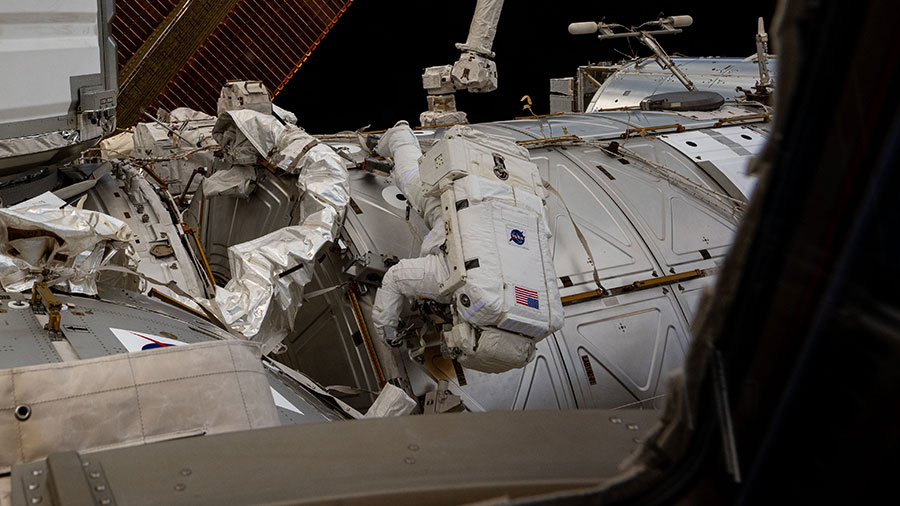
Astronaut Butch Wilmore works outside the space station during a five-hour and 26-minute spacewalk swabbing external surfaces searching for microorganisms on Jan. 30, 2025.
The Expedition 72 crew kicked off the first week in February cleaning up after last week’s spacewalk and continuing its space agriculture and microgravity physics experiments. Other International Space Station science objectives planned on Monday included human research while the orbital residents kept up the maintenance of the orbital outpost.
NASA astronauts Suni Williams and Butch Wilmore, station Commander and Flight Engineer respectively, are cleaning up following the Jan. 30 spacewalk to remove radio communications hardware and search for microorganisms outside the space station. Williams worked in the Harmony module disassembling the radio frequency group antenna assembly that she removed during the five-hour and 26-minute spacewalk. Wilmore serviced the spacesuits that he and Williams wore last week cleaning and reconfiguring suit cooling loops as well as checking the suits’ electrical components.
NASA Flight Engineer Nick Hague began his day assisting Williams with the radio hardware teardown work in Harmony and packing the gear for stowage. Afterward, Hague moved to the Kibo laboratory module refilling water inside the JAXA’s (Japan Aerospace Exploration Agency) Plant Experiment Unit. The small botany research facility, located in Kibo’s Cell Biology Experiment Facility, is supporting an investigation exploring how ultraviolet radiation and weightlessness affect plant growth to learn how to grow food and sustain crews on long-term mission to the Moon, Mars, and beyond.
NASA Flight Engineer Don Pettit focused on space physics inside Kibo’s Multi-Purpose Small Payload Rack (MSPR) during the first half of his shift. He opened up the MSPR and swapped samples inside its Electrostatic Levitation Furnace that can safely heat materials above 2,000 degrees Celsius to measure their thermophysical properties, as well as synthesize new materials in microgravity. Pettit then joined after the crew’s lunchtime and trained to use ultrasonic inspection hardware.
Roscosmos Flight Engineers Ivan Vagner and Alexey Ovchinin participated in a test to understand how and improve the way international crews communicate with mission controllers from around the world. Ovchinin then spent the last half of his shift practicing on a computer futuristic spacecraft and robotic piloting techniques crews may use on potential planetary missions. Flight Engineer Aleksandr Gorbunov spent his day inspecting and photographing cargo stowage areas in the Zvezda service module and testing Roscosmos life support gear.