NASA Data Shows July 22 Was Earth’s Hottest Day on Record

NASA Data Shows July 22 Was Earth’s Hottest Day on Record

Data visualization of monthly temperatures over time. The X-axis shows months of the year and the Y-axis shows temperature in degrees Celsius, running from below 12 to above 17. A thick section of lines in white indicates data from the years 1980 to 2022. A pink line that rises above the  white lines represents the year 2023. And crisscrossing but mostly above that is a red line representing 2024 through June, with the month of July marked in purple, rising above everything else, to above 17 degrees Celsius.
Daily global average temperature values from MERRA-2 for the years 1980-2022 are shown in white, values for the year 2023 are shown in pink, and values from 2024 through June are shown in red. Daily global temperature values from July 1-July 23, 2024, from GEOS-FP are shown in purple.
NASA/Global Modeling and Assimilation Office/Peter Jacobs

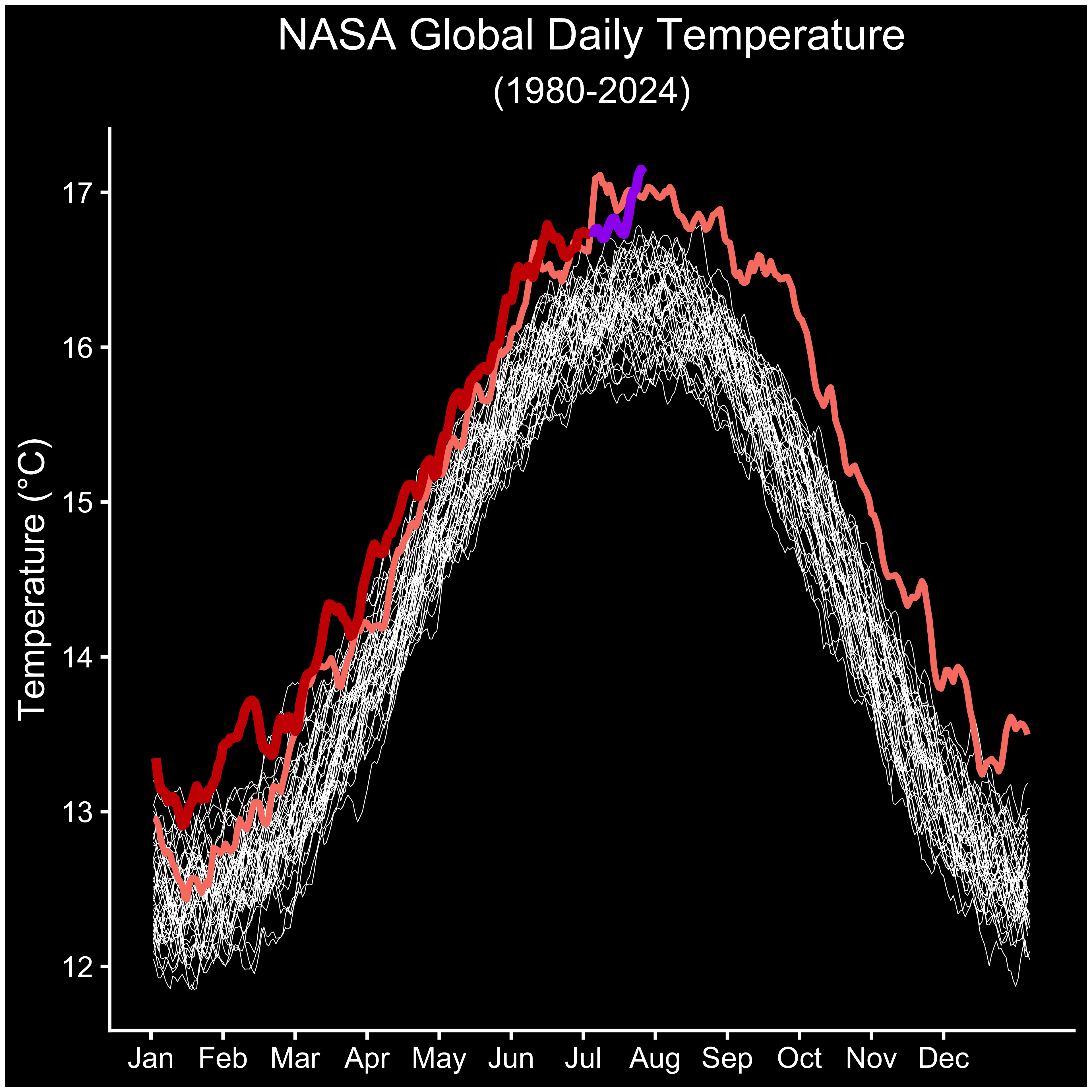
July 22, 2024, was the hottest day on record, according to a NASA analysis of global daily temperature data. July 21 and 23 of this year also exceeded the previous daily record, set in July 2023. These record-breaking temperatures are part of a long-term warming trend driven by human activities, primarily the emission of greenhouse gases. As part of its mission to expand our understanding of Earth, NASA collects critical long-term observations of our changing planet. 

“In a year that has been the hottest on record to date, these past two weeks have been particularly brutal,” said NASA Administrator Bill Nelson. “Through our over two dozen Earth-observing satellites and over 60 years of data, NASA is providing critical analyses of how our planet is changing and how local communities can prepare, adapt, and stay safe. We are proud to be part of the Biden-Harris Administration efforts to protect communities from extreme heat.”

This preliminary finding comes from data analyses from Modern-Era Retrospective analysis for Research and Applications, Version 2 (MERRA-2) and Goddard Earth Observing System Forward Processing (GEOS-FP) systems, which combine millions of global observations from instruments on land, sea, air, and satellites using atmospheric models. GEOS-FP provides rapid, near-real time weather data, while the MERRA-2 climate reanalysis takes longer but ensures the use of best quality observations. These models are run by the Global Modeling and Assimilation Office (GMAO) at NASA’s Goddard Space Flight Center in Greenbelt, Maryland.

Daily global average temperature values from MERRA-2 for the years 1980-2022 are shown in white, values for the year 2023 are shown in pink, and values from 2024 through June are shown in red. Daily global temperature values from July 1 to 23, 2024, from GEOS-FP are shown in purple. The results agree with an independent analysis from the European Union’s Copernicus Earth Observation Programme. While the analyses have small differences, they show broad agreement in the change in temperature over time and hottest days.

The latest daily temperature records follow 13 months of consecutive monthly temperature records, according to scientists from NASA’s Goddard Institute for Space Studies in New York. Their analysis was based on the GISTEMP record, which uses surface instrumental data alone and provides a longer-term view of changes in global temperatures at monthly and annual resolutions going back to the late 19th century.

Media Contact:

Liz Vlock
NASA Headquarters, Washington
202-358-1600
elizabeth.a.vlock@nasa.gov

Share

Details

Last Updated

Jul 29, 2024

Editor
Jennifer R. Marder
Location
Goddard Space Flight Center

Powered by WPeMatico

Get The Details…
Jennifer R. Marder

Managing Heat

Managing Heat

4 min read

Preparations for Next Moonwalk Simulations Underway (and Underwater)

Science in Space: July 2024

This time of year, managing heat is on everyone’s mind. Especially now, as May 2024 marked a full year of record-high monthly temperatures – an unprecedented streak, according to scientists from NASA’s Goddard Institute for Space Studies in New York.

NASA experts analyze data from thousands of land-, sea-, and sky-based instruments to calculate Earth’s global temperature. Knowing how hot it is helps scientists, health care workers, and public officials plan for and respond to the heat’s effects on people and infrastructure.

Crew members on the International Space Station deal with a different type of heat – that generated by electronics, life support systems, and other equipment. Managing this heat is essential to the operation of the spacecraft and the health and safety of its occupants.

Taking out the heat

A suitcase-sized piece of equipment sitting on a blue tabletop has a copper-colored frame and a metal box on the closest end with multiple nozzles and cords. A clear tube the length of the hardware is filled with small white beads. A person wearing a white lab coat and blue gloves is visible from the shoulders down behind the equipment.
Hardware for the packed bed water recovery reactor experiment. The packing media is visible in the long clear tube.
NASA

Packed bed reactors (PBRs) are structures packed with beads of different materials to increase contact between a liquid and a gas flowing through them. They are widely used for many applications, including thermal control or heat management, life support systems, and water filtration and offer low power consumption, compact size, and reliability. Packed Bed Reactor Experiment: Water Recovery Series (PBRE-WRS) continues evaluation of how microgravity affects the performance of different packing media. The material used and the shape and size of the beads all contribute to the effectiveness of heat exchange in a PBR. This investigation could inform the design and operation of these systems in microgravity and on the Moon and Mars and lead to improvements in this technology for applications on Earth such as water purification and cooling systems.

Previous investigations, PBRE and PBRE-2, provided fundamental understanding of simultaneous gas and liquid flow through PBRs in microgravity. This improved understanding helps to support development of more efficient and lightweight thermal management and life support systems for future missions.

Boiling heat away

In this video from the FBCE, as liquid begins to boil, small bubbles form at the heated surface (top of the image) and grow larger over time.
NASA

As electronic devices add more features, they generate more heat, which becomes increasingly challenging to remove. Flow boiling is a method of thermal management that uses this heat to boil a moving liquid and generate vapor bubbles that lift the heat from the surface, then change back to a liquid via condensation. But using boiling for heat management is less efficient in microgravity because, in the absence of buoyancy, bubbles grow larger and remain near the surface.

The Flow Boiling and Condensation Experiment (FBCE) tested a model for a flow boiling and condensation facility for the space station. Researchers identified important factors affecting this process in microgravity and how they differ from those on Earth. The findings could help researchers identify ways to improve the operation of these systems in microgravity.

This research also led to development of an artificial neural network (ANN) trained on data from the FBCE experiment to predict heat flow and transfer for use in the design and analysis of thermal systems. ANNs are a type of artificial intelligence made of computational units similar to neurons in the nervous systems of living things.

Cassada is wearing a blue polo shirt with a US flag on the sleeve and an Expedition patch on the chest. He is smiling at the camera and holding the round metal cap from a sleeve of the equipment in front of him, which has a large clear box with wires and digital readouts visible inside it and a panel of switches above it. There are coils of white, green, and red wires above Cassada’s head.
NASA astronaut Josh Cassada works on the PFMI-ASCENT investigation.
NASA

The PFMI-ASCENT investigation found that adding microscopic teeth or rachets to a surface caused more bubbles to form and increased the transfer of heat. This finding helps further improve flow boiling systems used to remove heat from electronics in space.

Going with the flow

A clear tube fills the image. The tube is filled with a red liquid with large bubbles in it that resemble a bunch of grapes. The background is blurred.
Close-up view of the Capillary Flow Experiment-2 test chamber.
NASA

Liquids behave differently in space than they do on Earth. Capillary Flow Experiment-2 studied wetting, or a liquid’s ability to spread across a surface, in different container shapes in microgravity. Results showed that models adequately predict liquid flow for various container shapes. These predictions support improved design of systems that process liquids aboard spacecraft, including systems for thermal control.

Melissa Gaskill

International Space Station Research Communications Team

NASA’s Johnson Space Center

Search this database of scientific experiments to learn more about those mentioned in this article.

Powered by WPeMatico

Get The Details…
cgetteau

NASA, JAXA Bounce Laser Beam Between Moon’s Surface and Lunar Orbit

NASA, JAXA Bounce Laser Beam Between Moon’s Surface and Lunar Orbit

NASA’s LRO (Lunar Reconnaissance Orbiter) has twice transmitted a laser pulse to a cookie-sized retroreflector aboard JAXA’s (Japan Aerospace Exploration Agency) SLIM lander on the Moon and received a return signal.

As LRO passed 44 miles above SLIM (Smart Lander for Investigating Moon) during two successive orbits on May 24, 2024, it pinged the lander with its laser altimeter instrument as it had done eight times before. But, on these two attempts, the signal bounced back to LRO’s detector.

This was an important accomplishment for NASA because the device is not in an optimal position. Retroreflectors are typically secured to the top of landers, giving LRO a 120-degree range of angles to aim toward when sending laser pulses to the approximate location of a retroreflector. However, the SLIM lander had settled on the surface with its top facing sideways, limiting LRO’s range.

To boost the chances of reaching their target, the LRO team worked with JAXA to determine the exact location and orientation of SLIM. Then, NASA engineers predicted when LRO’s orbit trajectory would bring it to coordinates that would give it the best chance of reaching SLIM’s retroreflector with the laser beams.

SLIM on the lunar surface captured by the LEV-2 (SORA-Q) rover.

“LRO’s altimeter wasn’t built for this type of application, so the chances of pinpointing a tiny retroreflector on the Moon’s surface are already low,” said Xiaoli Sun, who led the team that built SLIM’s retroreflector at NASA’s Goddard Space Flight Center in Greenbelt, Maryland, as part of a partnership between NASA and JAXA.

“For the LRO team to have reached a retroreflector that faces sideways, instead of the sky, shows that these little devices are incredibly resilient,” Sun said.

SLIM touched down on the Moon’s surface on Jan. 20. The retroreflector that hitched a ride with the lander, called a Laser Retroreflector Array, is one of the six NASA has sent to the Moon aboard private and public landers, and the second to bounce signal back to LRO’s altimeter.

The first time a laser beam was transmitted from LRO to a NASA retroreflector and back was on Dec. 12, 2023, when LRO pinged ISRO’s (Indian Space Research Organisation) Vikram lander. LRO has since exchanged laser pings with Vikram three more times.

NASA’s retroreflector has eight quartz corner-cube prisms set into a dome-shaped aluminum frame that is 2 inches wide. With no power or maintenance required, retroreflectors can last on the Moon’s surface for decades and thus provide reliable beacons for future missions.

Three views are shown in one image in varying levels of detail. On the left is a metallic structure shaped like a box with wings. It stands on top of a base, with a green floor and metallic wall visible in the background. A small red box encloses a feature that is zoomed into in another image to the right of the main one. Below that, a final image is shown, with the object visible up close, with gold metallic material behind it. The object is round, metallic, covered in eight holes that take up the entire surface.
NASA’s Laser Retroreflector Array installed on JAXA’s SLIM lander before launch.

The retroreflectors could guide Artemis astronauts to the surface in the dark, for example, or mark the locations of spacecraft already on the surface to help astronauts and uncrewed spacecraft land near them.

LRO’s laser altimeter, the only laser instrument orbiting the Moon for now, was designed to map the Moon’s topography to prepare for missions to the surface — not to point to within 1/100th of a degree of a retroreflector, which is what LRO engineers are trying to do with every ping.

LRO is managed by NASA’s Goddard Space Flight Center in Greenbelt, Maryland, for the Science Mission Directorate at NASA Headquarters in Washington. Launched on June 18, 2009, LRO has collected a treasure trove of data with its seven powerful instruments, making an invaluable contribution to our knowledge about the Moon. NASA is returning to the Moon with commercial and international partners to expand human presence in space and bring back new knowledge and opportunities.


By Lonnie Shekhtman
NASA’s Goddard Space Flight Center, Greenbelt, Md.      
            
 
Media Contact:
Nancy Neal Jones
NASA’s Goddard Space Flight Center, Greenbelt, Md.

Powered by WPeMatico

Get The Details…

Earth to Gateway: Electric Field Tests Enhance Lunar Communication

Earth to Gateway: Electric Field Tests Enhance Lunar Communication

2 min read

Preparations for Next Moonwalk Simulations Underway (and Underwater)

Left: An artist's rendering of Gateway space station's Power and Propulsion Element (PPE) and Habitation and Logistics Outpost (HALO) in lunar orbit. The image showcases the space station's intricate design, including solar panels, antennas, and docking ports against a starry backdrop. Right: A photograph of an antenna being tested in an anechoic chamber at NASA’s Johnson Space Center. The antenna, mounted on a stand, is positioned in a room lined with blue, sound-absorbing foam.
An artist’s rendering of NASA’s Gateway space station in lunar orbit, featuring the Power and Propulsion Element (PPE) and Habitation and Logistics Outpost (HALO), left, and a photograph of an antenna undergoing testing in an anechoic chamber at NASA’s Johnson Space Center, right.
NASA/Robert Markowitz

Engineers at NASA’s Johnson Space Center recently began electric field testing on representative communications hardware for Gateway, humanity’s first space station to orbit the Moon.

An orbiting laboratory for deep space science and a staging ground for lunar exploration, Gateway will help NASA and its international partners establish a sustained human presence on and around the Moon in preparation for the next giant leap – human exploration of Mars.

High-gain antennas are an important component of Gateway’s communication and tracking system that connects operations across the vast distances of the lunar South Pole region, to Gateway in orbit around the Moon, to Earth, and back again.  

NASA is conducting rigorous testing on the electric field levels radiated by the antennas to ensure safe and efficient communication and to avoid any interference with Gateway’s crew and equipment. By validating simulation models to accurately predict electric field levels, NASA can establish precise safety zones around the K/Ka-band parabolic reflector antennas to protect astronauts and hardware without sacrificing high-rate communications.

During the meticulous testing process, engineers use electric field and waveguide probes, which measure the strength and quality of electromagnetic signals, to scan the near fields of a representative high-gain antenna. Robotic arms and optical tracking systems provide the precise measurements needed for model validation. The testing is being conducted in an anechoic chamber, a specialized room that provides a controlled environment for measurements of electromagnetic waves.

“We are sharpening our pencil in conducting model validation measurements – ensuring high accuracy in the analysis of electric fields radiated by the high-gain antennas on Gateway,” said Timothy Kennedy, one of the NASA engineers overseeing the tests. “This enables reduced margins on antenna masking needed to protect equipment and crew, while maximizing communication coverage.”

Findings are expected to enhance NASA’s understanding of the electric field levels emitted by Gateway’s antennas and inform critical decisions for operating them safely during Artemis missions, ensuring that Gateway is a safe home for astronauts around the Moon.

Share

Details

Last Updated

Jul 29, 2024

Editor
Briana R. Zamora
Contact
Briana R. Zamora

Powered by WPeMatico

Get The Details…
Dylan Connell